
Mechanical password device

A cryptographic device and mechanical technology, applied in the field of locks, can solve problems such as easy wear and tear of lock bars and lock plates, and reduced precision

Active Publication Date: 2021-08-20
浙江德施曼科技智能股份有限公司
View PDF3 Cites 1 Cited by
  • Summary
  • Abstract
  • Description
  • Claims
  • Application Information

AI Technical Summary

Problems solved by technology

[0002] Now many door locks all adopt mechanical code to unlock, and patent CN207332499U provides a kind of mechanical code lock, in the code lock of this structure, two lock bars ( The reference number in the literature is 31), and two springs are arranged between the two lock bars, and the two springs have a tendency to bounce off, and when the two springs push the two lock bars, the dead bolt can move freely , the defect of the mechanical combination lock of this structure is that since the lock plate and the lock bar adopt the matching method of the triangular notch and the triangular protrusion, this triangular contact mode is very easy to wear the lock bar and the lock plate, lead to reduced accuracy

Method used


Image

  • Mechanical password device
  • Mechanical password device
  • Mechanical password device

Examples


Embodiment Construction

[0036] Below in conjunction with each accompanying drawing, the present invention is described in detail.

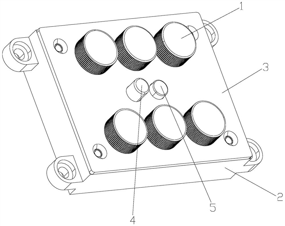
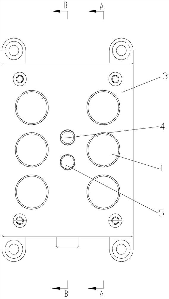
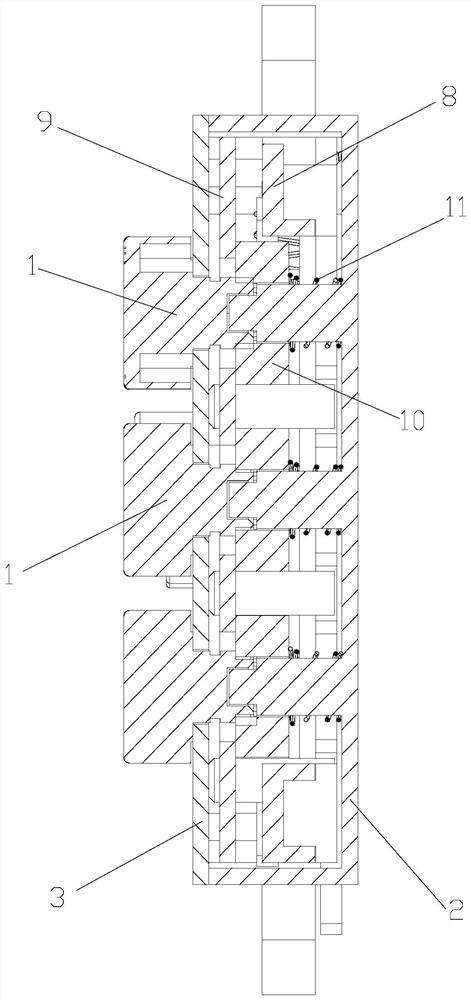
[0037] as attached figure 1 , attached figure 2 , attached image 3 and attached Figure 4 As shown, a mechanical password device includes a base 2, a deadbolt plate 7 and a deadbolt spring 6, the deadbolt plate 7 is slidably mounted on the base 2, and the two ends of the deadbolt spring 6 are against the deadbolt plate 7 and the deadbolt spring 6 respectively. The base 2 also includes a limiting plate 8, a turntable 1, a combination wheel 10 and a clutch spring 14, the turntable 1 is installed on the base 2, the combination wheel 10 is matched with the turntable 1, the limit plate 8 is arranged on the base 2, and the clutch The spring 14 is arranged in the base 2, and the two ends of the clutch spring 14 are against the limit plate 8 and the base 2 respectively, the password wheel 10 is provided with an inner concave 1001, and the limit plate 8 is provided with a co...


PUM


Abstract

The invention discloses a mechanical password device. The mechanical password device comprises a base, a spring bolt plate and a spring bolt spring, wherein the spring bolt plate is mounted on the base in a sliding manner; the two ends of the spring bolt spring are respectively propped against the spring bolt plate and the base; the mechanical password device further comprises a limiting plate, a rotating disc, a password wheel and a clutch spring; the rotating disc is mounted on the base; the password wheel is matched with the rotating disc; the limiting plate is arranged on the base; the clutch spring is arranged in the base; the two ends of the clutch spring are respectively propped against the limiting plate and the base; an inner concave part is formed in the password wheel; and a bulge matched with the inner concave part is arranged on the limiting plate. The mechanical password device has the benefits that the password wheel is not in friction contact with the limiting plate during the rotating process, so that the password wheel is not abraded with the limiting plate during the rotating process, and the good matching precision between the password wheel and the limiting plate is ensured.

Description

technical field [0001] The invention relates to the field of locks, in particular to a mechanical password device. Background technique [0002] Many door locks all adopt mechanical code to unlock now, and patent CN207332499U provides a kind of mechanical coded lock, in the coded lock of this structure, by setting two lock bars ( The reference number in the document is 31), and two springs are arranged between the two lock bars, and the two springs have a tendency to spring apart. When the two springs bounce the two lock bars, the dead bolt can move freely , the defect of the mechanical combination lock of this structure is that since the lock plate and the lock bar adopt the matching method of the triangular notch and the triangular protrusion, this triangular contact mode is very easy to wear the lock bar and the lock plate, lead to reduced accuracy. Contents of the invention [0003] Aiming at the above problems, the present invention proposes a mechanical encryption ...

Claims


Application Information

Patent Timeline
IPC IPC(8): E05B37/12E05B37/00E05B15/00
CPCE05B37/12E05B37/001E05B15/00
Inventor 余开军黄兴主祝志凌桑胜伟叶飞邓业豪
Owner 浙江德施曼科技智能股份有限公司
Learn More