
Vaccine production equipment

A vaccine production and equipment technology, applied in biochemical equipment and methods, biochemical instruments, biomass post-processing, etc., can solve the problems of inconvenient cleaning, fixed frame occupying workbench space, etc., and achieve the effect of convenient cleaning

Inactive Publication Date: 2021-08-20
罗丽萍
View PDF0 Cites 0 Cited by
  • Summary
  • Abstract
  • Description
  • Claims
  • Application Information

AI Technical Summary

Problems solved by technology

[0004] In order to make up for the above deficiencies, the present invention provides a vaccine production equipment, which solves the problems of the fixed frame occupying the workbench space and inconvenient cleaning

Method used


Image

  • Vaccine production equipment
  • Vaccine production equipment
  • Vaccine production equipment

Examples


Embodiment 1

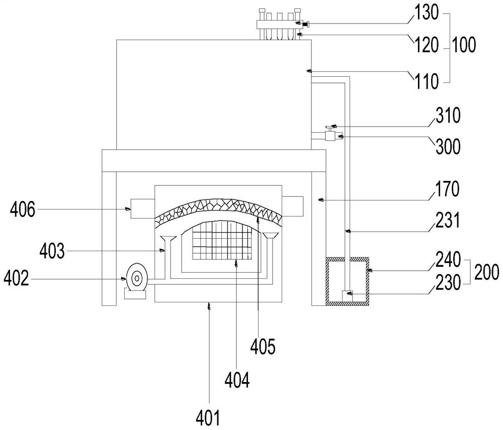
[0039] see figure 1, the present invention provides a technical solution: a vaccine production equipment includes a fixing mechanism 100 and a cleaning mechanism 200 , wherein the cleaning mechanism 200 is fixed in the fixing mechanism 100 .

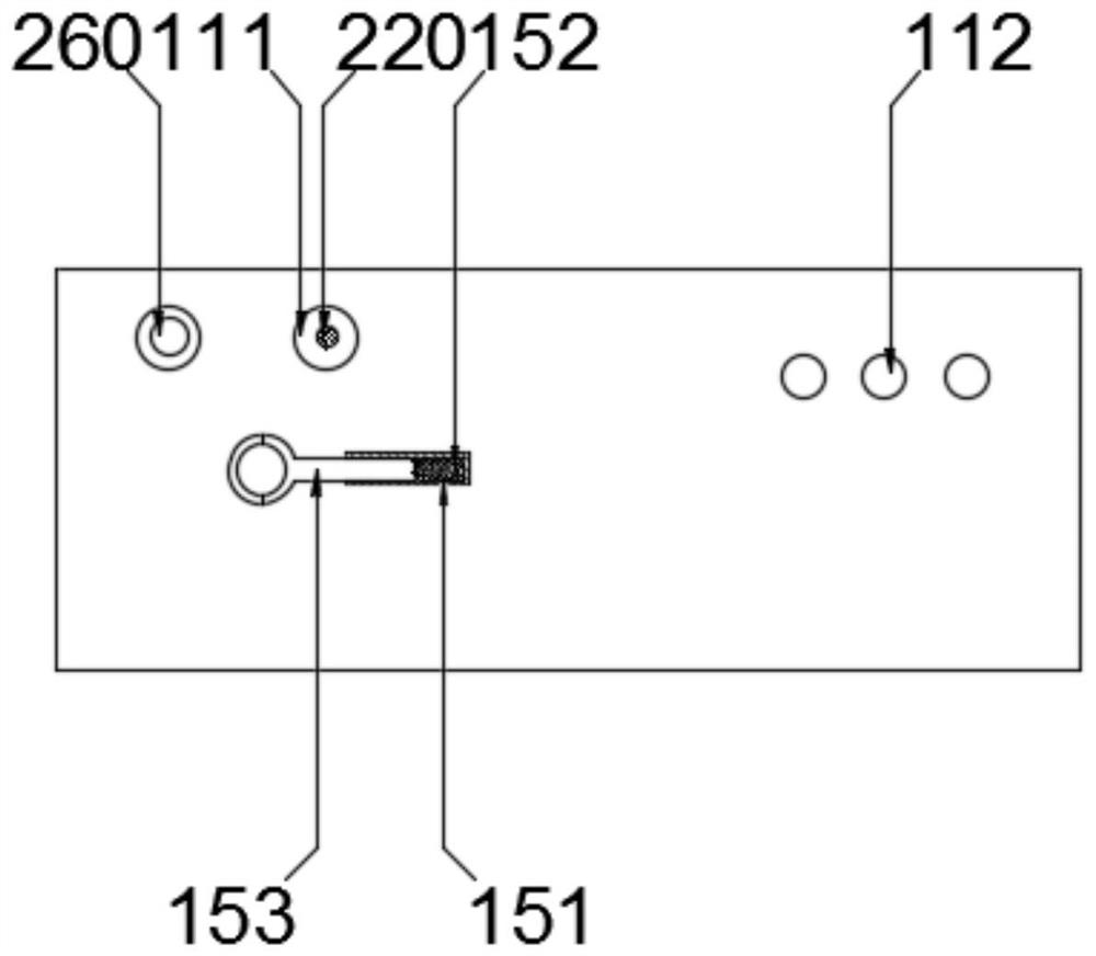
[0040] see figure 1 , 2 And 4, the fixing mechanism 100 includes a cleaning box 110, a first pole 120, a fixed plate 130, a test tube 140, a telescopic rod 150 and a block 160, and the surface of the cleaning box 110 is provided with three first through holes 111, the first through hole The diameter of 111 is larger than that of the test tube 140. There are two first support rods 120, and the two first support rods 120 are fixed on the surface of the cleaning box 110 at intervals. 112, the groove 112 is arranged under the test tube 140, the groove 112 is convenient for fixing the test tube 140, the fixing plate 130 is slidably sleeved on the first support rod 120, and the end of the first support rod 120 away from the cleaning box 110 ...

Embodiment 2

[0045] see figure 1 , the present invention provides a technical solution: a vaccine production equipment includes a fixing mechanism 100 and a cleaning mechanism 200 , wherein the cleaning mechanism 200 is fixed in the fixing mechanism 100 .

[0046] see figure 1 , 2 And 4, the fixing mechanism 100 includes a cleaning box 110, a first pole 120, a fixed plate 130, a test tube 140, a telescopic rod 150 and a block 160, and the surface of the cleaning box 110 is provided with three first through holes 111, the first through hole The diameter of 111 is larger than that of the test tube 140. There are two first support rods 120, and the two first support rods 120 are fixed on the surface of the cleaning box 110 at intervals. 112, the groove 112 is arranged under the test tube 140, the groove 112 is convenient for fixing the test tube 140, the fixing plate 130 is slidably sleeved on the first support rod 120, and the end of the first support rod 120 away from the cleaning box 110...


PUM


Abstract

The invention provides vaccine production equipment. The equipment comprises a fixing mechanism, a cleaning mechanism and a drying mechanism, the fixing mechanism comprises a cleaning box, two first supporting rods, a fixing plate, a test tube, a telescopic rod piece and a clamping block, three first through holes are arranged in the surface of the cleaning box, the first supporting rods are sleeved with the fixing plate in a sliding mode, a bolt is arranged on one side of the fixing plate, a water tank is arranged on the outer side of the cleaning box, a water pump is fixed in the water tank and communicates with the water pipe, a motor is fixed in the cleaning box and arranged below one of the first through holes, one end of a brush roller is fixed to the output end of the motor, and the other end of the brush roller extends the out of the first through holes. The surface of the vaccine production equipment is provided with a fixing part and a cleaning part, so that the vaccine production equipment does not occupy operation space and is convenient to clean; and the drying mechanism is arranged below the cleaning mechanism to synchronously dry the cleaned vaccines, so that the vaccine production efficiency is improved.

Description

technical field [0001] The invention relates to the field of vaccine production, in particular to a vaccine production equipment. Background technique [0002] Vaccines refer to vaccine-like preventive biological products used for human vaccination in order to prevent and control the occurrence and prevalence of infectious diseases. Biological products refer to preparations for prevention, diagnosis and treatment made from microorganisms or their toxins, enzymes, human or animal serum, cells, etc. Biological products for vaccination include vaccines, bacterins and toxoids. Among them, those made of germs are called bacterins; those made of viruses, rickettsia, and spirochetes are called vaccines, sometimes collectively referred to as vaccines. [0003] During the production process of the vaccine, several steps such as sampling and separation are required, and the test tubes are often used multiple times. When the test tubes are used on the operating table, there are fixed...

Claims


Application Information

Patent Timeline
Patent Type & Authority Applications(China)
IPC IPC(8): C12M1/26C12M1/00C12M3/00B08B9/28B08B9/34B08B9/36B08B13/00
CPCB08B9/28B08B9/34B08B9/36B08B13/00C12M23/46C12M23/48C12M33/00C12M39/00C12M47/14
Inventor 罗丽萍
Owner 罗丽萍
Learn More