
Electro-tricycle carriage with auxiliary loading structure,

A technology for electric tricycles and tricycles, which is applied to vehicles with wheels, vehicles used for freight, vehicles with loading ramps, etc., can solve the problems of increasing the work intensity of staff and inconvenient for staff to load and unload goods.

Inactive Publication Date: 2021-08-20
徐州彭友车辆科技有限公司
View PDF6 Cites 9 Cited by
  • Summary
  • Abstract
  • Description
  • Claims
  • Application Information

AI Technical Summary

Problems solved by technology

[0006] In order to make up for the deficiencies of the prior art, the inner bottom surface of the compartment of the existing electric tricycle is provided with anti-slip lines. Although the stability of the transported goods is improved, it is not convenient for the staff to carry out loading and unloading of larger goods. To solve the problem of the working strength of the staff, the present invention proposes an electric tricycle compartment with an auxiliary loading structure

Method used


Image

  • Electro-tricycle carriage with auxiliary loading structure,
  • Electro-tricycle carriage with auxiliary loading structure,
  • Electro-tricycle carriage with auxiliary loading structure,

Examples


Embodiment 1

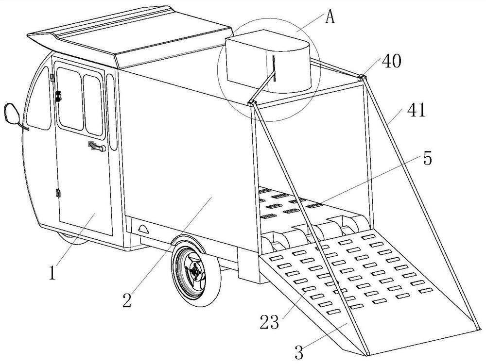
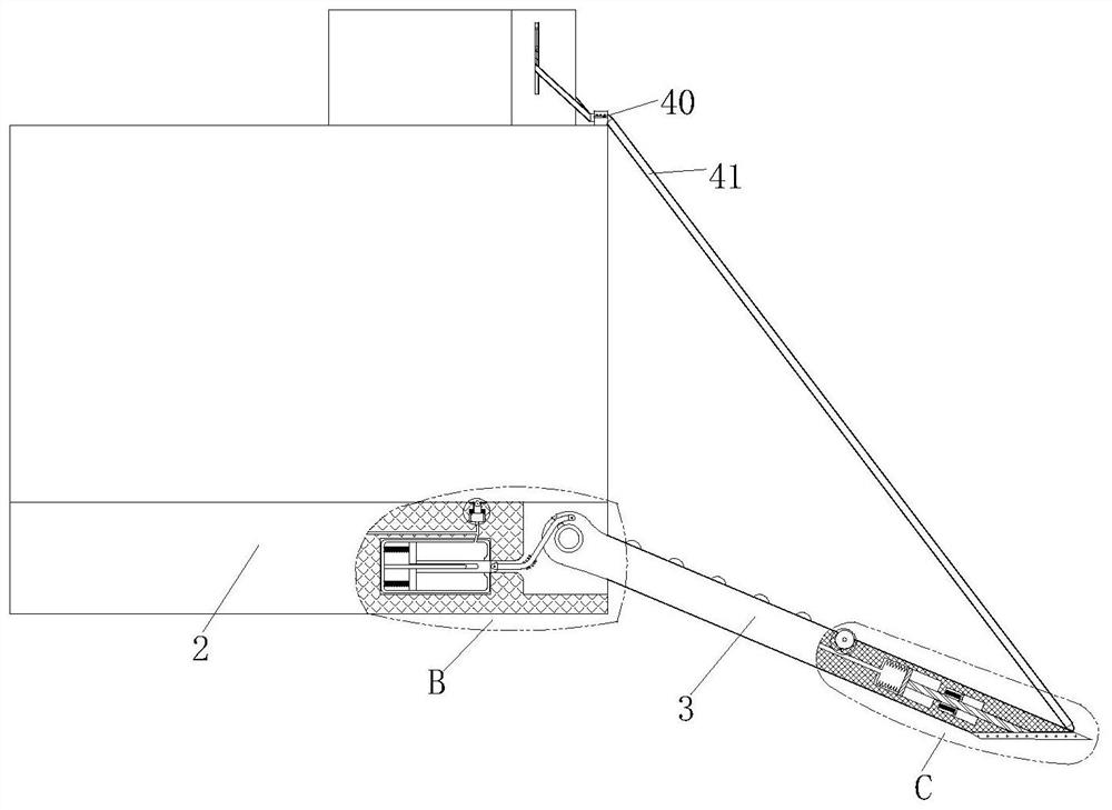
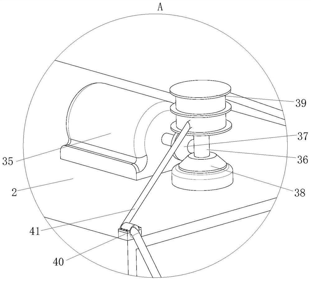
[0031] see Figure 1-7 As shown, an electric tricycle compartment with an auxiliary loading structure includes a tricycle body 1, a compartment 2, a rear plate 3, a hydraulic structure, a slide table 4 and rollers 5; the top surface of the tricycle body 1 is fixed to the compartment 2. The rear part of the compartment 2 is hinged to the rear panel 3, and a hydraulic structure is arranged inside the bottom wall of the compartment 2, and a plurality of lifting grooves 6 are evenly opened on the top surface of the bottom wall of the compartment 2, and the inside of the lifting groove 6 Slidingly install the sliding table 4, the top surface of the sliding table 4 is provided with a notch, the inside of the notch is rotated to install the roller 5, the power end of the hydraulic structure is connected to the hinge position of the rear plate 3, the execution of the hydraulic structure The end is connected to the bottom of the slide table 4; during work, the inner bottom surface of t...

Embodiment 2

[0041] see Figure 8 As shown, the outer ring of the piston 8 is provided with a plurality of ring grooves 42, the inside of the ring grooves 42 is fixedly connected with a sealing ring 43, the middle part of the sealing ring 43 is provided with a main air ring 44, and the middle part of the sealing ring 43 A plurality of auxiliary air rings 45 are arranged on the outer ring, and the auxiliary air rings 45 communicate with the main air ring 44; when working, the piston 8 and the hydraulic cylinder 7 squeeze the sealing ring 43, so that the sealing ring 43 is compressed and deformed, so that the main air ring 44 is compressed with the auxiliary air ring 45, so that the sealing ring 43 is closely attached to the inner wall of the hydraulic cylinder 7, preventing hydraulic oil from entering one side of the extension spring 12, thereby increasing the oil pressure of the hydraulic structure.

[0042] Working principle: First, the motor 35 rotates in the opposite direction, and thro...


PUM


Abstract

The invention belongs to the field of electro-tricycles, and particularly relates to an electro-tricycle carriage with an auxiliary loading structure, which comprises a tricycle body, a carriage, a rear plate, a hydraulic structure, a sliding table and rollers, The carriage is fixedly connected to the top face of a tricycle body, a rear plate is hinged to the tail of the carriage, a hydraulic structure is arranged in the bottom wall of the carriage, a plurality of lifting grooves are evenly formed in the top face of the bottom wall of the carriage, sliding tables are slidably installed in the lifting grooves, notches are formed in the top faces of the sliding tables, and rolling wheels are rotatably installed in the notches. The power end of the hydraulic structure is connected with the hinged position of the rear plate, and the execution end of the hydraulic structure is connected with the bottom of the sliding table. When loading and unloading are needed, the rear plate is opened, the sliding table is lifted through the hydraulic structure, the rolling wheels are lifted, the friction force between goods and the carriage is reduced, and the loading and unloading workload of workers is facilitated.

Description

technical field [0001] The invention belongs to the field of electric tricycles, in particular to an electric tricycle compartment with an auxiliary loading structure. Background technique [0002] With its strong applicability, flexible maneuverability, simple maintenance, convenient maintenance, and low price, electric tricycles can flexibly walk through narrow roads; with the increasingly vigorous development of the online shopping industry, electric tricycles are widely used in express delivery. Short distance transportation and distribution. [0003] There have also been some technical solutions about the electric tricycle compartment with auxiliary loading structure in the prior art, such as the application publication number is CN110667756, a kind of electric tricycle compartment with auxiliary loading structure, including the box body, the front end of the box body The outer surface is connected with a door through a hinge, the outer surface of the front end of the ...

Claims


Application Information

Patent Timeline
Patent Type & Authority Applications(China)
IPC IPC(8): B62K7/04B60P1/43B60P1/52
CPCB62K7/04B60P1/435B60P1/52
Inventor 唐明芳
Owner 徐州彭友车辆科技有限公司
Learn More