
Laser drilling equipment for LCP flexible circuit board

A flexible circuit board, laser drilling technology, used in laser welding equipment, welding equipment, metal processing equipment and other directions, can solve the problems of easy to hit and low efficiency, and achieve the effect of avoiding deviation

Inactive Publication Date: 2021-08-20
聂三磊
View PDF0 Cites 1 Cited by
  • Summary
  • Abstract
  • Description
  • Claims
  • Application Information

AI Technical Summary

Problems solved by technology

[0004] In order to make up for the above deficiencies, the present invention provides a laser drilling equipment for LCP flexible circuit boards, which aims to improve the drilling equipment of some circuit boards. When drilling symmetrical holes, the holes are distributed sequentially, and the problem of low efficiency and easy drilling

Method used


Image

  • Laser drilling equipment for LCP flexible circuit board
  • Laser drilling equipment for LCP flexible circuit board
  • Laser drilling equipment for LCP flexible circuit board

Examples


Embodiment 1

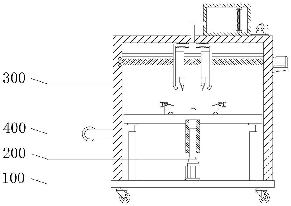
[0032] see Figure 1-5 , the present invention provides a technical solution: a laser drilling device for an LCP flexible circuit board includes a base 100 , a fixing assembly 200 and a laser drilling assembly 300 .

[0033] The fixing assembly 200 is used for fixing and clamping the workpiece, and the laser drilling assembly 300 is used for drilling.

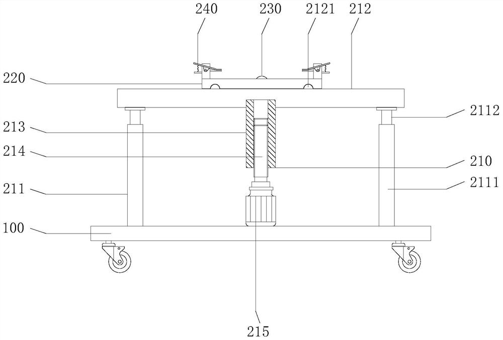
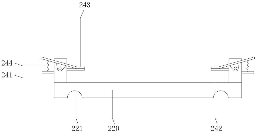
[0034] see figure 1 , 2And 3, the fixed assembly 200 includes a lifting member 210, a sliding table 220, an electric push rod 230 and a clamping member 240, the lifting member 210 is arranged on the top of the base 100, the sliding table 220 is arranged on the top of the lifting member 210, and the electric push rod 230 is arranged on The top of the lifting part 210, the sliding table 220 is fixedly connected to the movable end of the electric push rod 230, and the sliding table 220 is bolted or welded to the electric pushing rod 230. Specifically, the lifting part 210 includes a telescopic rod 211, a top plate 212, a threade...

Embodiment 2

[0037] see Figure 1-5 , the present invention provides a technical solution: a laser drilling device for an LCP flexible circuit board includes a base 100 , a fixing assembly 200 and a laser drilling assembly 300 .

[0038] The fixing assembly 200 is used for fixing and clamping the workpiece, and the laser drilling assembly 300 is used for drilling.

[0039] see figure 1 , 2 And 3, the fixed assembly 200 includes a lifting member 210, a sliding table 220, an electric push rod 230 and a clamping member 240, the lifting member 210 is arranged on the top of the base 100, the sliding table 220 is arranged on the top of the lifting member 210, and the electric push rod 230 is arranged on The top of the lifting part 210, the sliding table 220 is fixedly connected to the movable end of the electric push rod 230, and the sliding table 220 is bolted or welded to the electric pushing rod 230. Specifically, the lifting part 210 includes a telescopic rod 211, a top plate 212, a thread...


PUM


Abstract

The invention provides laser drilling equipment for an LCP flexible circuit board, and belongs to the technical field of circuit board processing. The laser drilling equipment for the LCP flexible circuit board comprises a base, a fixing assembly and a laser drilling assembly; the fixing assembly comprises a lifting part, a sliding table, an electric push rod and a clamping part; the lifting part is arranged at the top of the base; the laser drilling assembly comprises a shell, a two-way screw rod, a first motor, a moving block, a laser drill bit, a collecting box, a fan, a filter screen and an air guide pipe; and the shell is arranged at the top of the base. Through the arrangement of the shell, the two-way screw rod, the first motor, the moving block and the laser drill bit, symmetrical hole positions are effectively machined, and the situation that the symmetrical hole positions deviate is avoided to a great extent; and meanwhile, through the cooperative use of the collecting box, the fan, the filter screen and the air guide pipe, chippings generated during drilling are effectively collected, and the influence of chippings on the machining process is avoided to a certain extent.

Description

technical field [0001] The invention relates to the field of circuit board processing, in particular to a laser drilling device for an LCP flexible circuit board. Background technique [0002] The laser drilling device uses a high-power-density laser beam to irradiate the material to be processed, so that the material is quickly heated to the vaporization temperature, and evaporates to form holes. Laser drilling is the earliest practical laser processing technology, and it is also one of the main application fields of laser processing. [0003] At present, the laser drilling device of the LCP flexible circuit board in the prior art needs to be symmetrical because the holes of some LCP flexible circuit boards need to be symmetrical, and some equipment adopts a step-by-step method to drill holes sequentially, which has low work efficiency and is easy to cause uneven drilling positions. Symmetry affects product quality. Contents of the invention [0004] In order to make up...

Claims


Application Information

Patent Timeline
Patent Type & Authority Applications(China)
IPC IPC(8): B23K26/16B23K26/382B23K26/402B23K26/70
CPCB23K26/16B23K26/402B23K26/382B23K26/702
Inventor 聂三磊
Owner 聂三磊
Learn More