
Weldment cooling device for vacuum welding machining

A vacuum welding and cooling device technology, applied in auxiliary devices, welding equipment, metal processing equipment, etc., can solve the problems of poor cooling effect, affecting the appearance, and unable to realize fixed-point cooling of welds, etc.

Inactive Publication Date: 2021-08-20
THE SECOND XIANGYA HOSPITAL OF CENT SOUTH UNIV
View PDF1 Cites 0 Cited by
  • Summary
  • Abstract
  • Description
  • Claims
  • Application Information

AI Technical Summary

Problems solved by technology

The cooling effect of the device is poor, and the efficient cooling of the welded parts inside the vacuum welding pump cannot be achieved only by means of air cooling
[0004] At the same time, some of the cooling devices of vacuum welding pumps that exist at this stage not only use air cooling but also water cooling to achieve rapid cooling, but none of these cooling devices can achieve fixed-point cooling of the weld, and at the same time control and adjust the flow of solder, and melt the solder. Uneven cooling will lead to gaps and leaks inside, resulting in irregular flow of solder between base metals and affecting the appearance. At the same time, high-temperature water and gas after cooling work will be discharged directly, resulting in energy waste

Method used


Image

  • Weldment cooling device for vacuum welding machining
  • Weldment cooling device for vacuum welding machining
  • Weldment cooling device for vacuum welding machining

Examples


no. 1 example

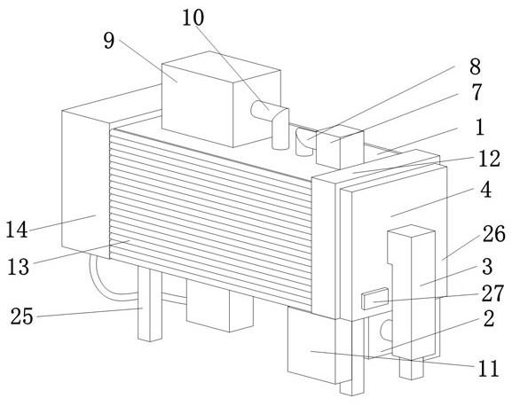
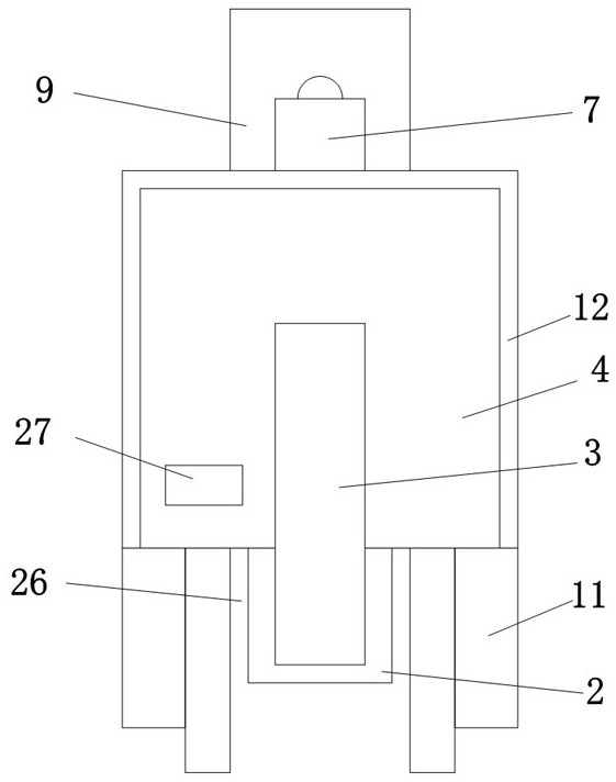
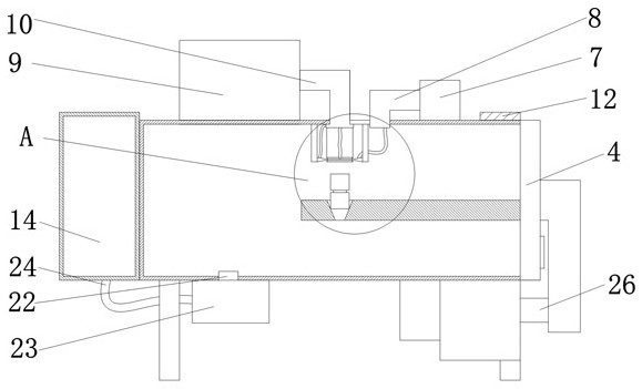
[0029] like Figure 1 to Figure 7 As shown, the present invention provides a welding piece cooling device for vacuum welding, comprising a vacuum box 1, one side of the vacuum box 1 is a feed port, the bottom of the vacuum box 1 is provided with a hydraulic connection device 26, and one part of the hydraulic connection device 26 is There is a sealed door 4 on the side, and the sealed door 4 is matched with the feed port. The opening of the sealed door 4 can realize the feeding of the inside of the vacuum box 1, and when the sealed door 4 and the vacuum box 1 are closed, the absolute inside of the vacuum box 1 is guaranteed. Airtight to prevent the outside air from entering the vacuum box 1 during the welding cooling process and causing pollution to the welding. The hydraulic connection device 26 includes a hydraulic cylinder 2, which is fixedly connected to the bottom of the vacuum box 1, and the output end of the hydraulic cylinder 2 is provided with a connection The rod 3 an...

no. 2 example

[0039] Based on the welding piece cooling device for vacuum welding processing provided in the first embodiment, only water cooling is used to cool the vacuum welding, the cooling efficiency is low, and the welding position cannot be cooled at a fixed point, and the molten solder 16 is solidified when it is solidified. Due to the different positions, the cooling efficiency of each part will be different, so that gaps and leaks will appear between the solidified solder 16 due to uneven cooling, which will affect the welding effect. When the common air cooling is used to cool the weld, Because the cooling gas blows the molten solder 16 by wind force to cause it to flow in all directions, or when the base material 15 and the solder 16 are tilted, the molten solder 16 will flow obliquely under its own gravity, thereby The welding position is uneven, which reduces the welding effect and affects the aesthetics of the welding. At the same time, the cooling liquid and cooling gas after...


PUM


Abstract

The invention belongs to the technical field of vacuum welding, and discloses a weldment cooling device for vacuum welding machining. The weldment cooling device comprises a vacuum box, one side of the vacuum box is provided with a feed inlet, the bottom of the vacuum box is provided with a hydraulic connecting device, one side of the hydraulic connecting device is provided with a sealing door, the sealing door is matched with the feed inlet, a controller is arranged on one side of the sealing door, a bearing plate is arranged on one side of the sealing door, a fixing hole is formed in the interior oof the bearing plate, two layers of base metals are arranged in the fixing hole, and welding flux is arranged between the base metals. According to the weldment cooling device for vacuum welding machining, uniform cooling of the vacuum box is achieved through cooling liquid, the air outlet amount of a first air injection gun and the air outlet amount of a second air injection gun can be controlled according to the temperature value detected by a first temperature sensor in a cooling liquid pipe, and therefore fixed-point efficient cooling is achieved, the cooling efficiency is improved, the cooling position of the welding flux is corrected, and gap holes in the interior of the welding flux are avoided; and meanwhile, heat can be recycled, and the resource utilization rate of the device is increased.

Description

technical field [0001] The invention belongs to the technical field of vacuum welding, in particular to a welding piece cooling device for vacuum welding processing. Background technique [0002] Vacuum brazing means that the workpiece is heated in a vacuum chamber, and it is mainly used for welding of high-quality products and easily oxidized materials. The vacuum brazing furnace includes a pressure vessel having a cylindrical side wall and a door sized and positioned to close one end of the cylindrical side wall. Workpiece handling systems are mounted on pressure vessel doors to support metal workpieces for heat treatment or brazing. The workpiece handling system includes means for rotating the workpiece during processing. The vacuum system can be connected to the workpiece, so that the pressure inside the workpiece is lower than the atmospheric pressure during the brazing process; the cooling device belongs to the field of production line auxiliary equipment, including ...

Claims


Application Information

Patent Timeline
Patent Type & Authority Applications(China)
IPC IPC(8): B23K3/08
CPCB23K3/085
Inventor 彭春艳
Owner THE SECOND XIANGYA HOSPITAL OF CENT SOUTH UNIV
Learn More