Transformer fire extinguishing device with opening operation

A technology for a fire extinguishing device and a transformer, applied in the field of electrical equipment and transformer fire extinguishing equipment, can solve problems such as hidden dangers, environmental pollution, easy fire spread, etc., and achieve the effect of reducing the supply of oxygen, reducing hidden dangers, and being beneficial to fire fighting.

Pending Publication Date: 2021-08-20
湖北鄂电德力电气有限公司
View PDF9 Cites 0 Cited by
  • Summary
  • Abstract
  • Description
  • Claims
  • Application Information

AI Technical Summary

Problems solved by technology

At present, fires in the outdoor distribution station area occur from time to time, and the fire in the outdoor distribution station area is mainly caused by the transformer 400. For the fire extinguishing of the transformer 400 in the outdoor distribution station area, the current method is generally to first use the gram rod to extinguish the fire. The transformer knife switch 401 is opened to cut off the power, and then the transformer 400 is extinguished manually on the ground or by climbing up the concrete pole 406. However, this fire extinguishing method has great potential safety hazards, and the fire extinguishing effect is not very satisfactory. It is easy to spread to the distribution cabinet 404 or other facilities around the transformer 400
In addition, when the transformer 400 catches fire, a large amount of smoke and dust will be generated, thereby causing great pollution to the environment

Method used


Image

  • Transformer fire extinguishing device with opening operation
  • Transformer fire extinguishing device with opening operation
  • Transformer fire extinguishing device with opening operation

Examples


Embodiment Construction

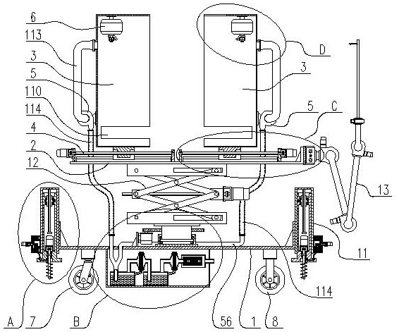
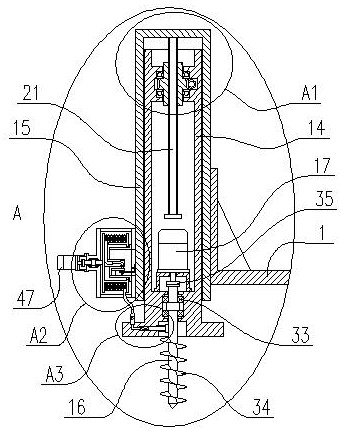
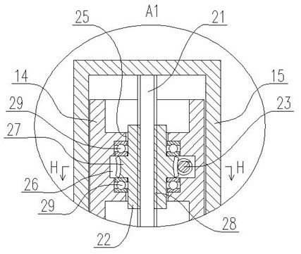
[0042] Depend on figure 1 As shown, the transformer fire extinguishing device with opening operation includes a vehicle frame 1, a platen 2, a pair of casings 3, a pair of lateral movement mechanisms 4, a pair of induced draft fans 5, and a pair of suspension type Dry powder fire extinguisher 6, universal wheel 7, walking wheel 8, smoke and dust purification mechanism 10, supporting grounding mechanism 11, scissor lifting mechanism 12 and opening mechanism 13, said universal wheel 7 and walking wheel 8 are installed on the frame 1 bottom, by Figure 2 to Figure 7 As shown, the supporting grounding mechanism 11 includes a leg 14, a square tube 15, a retracting and releasing mechanism, a ground rod 16, a second motor 17, a spring 18, a conductive voltage block 19 and a terminal 20, and the square tube 15 is fixedly installed On the vehicle frame 1, the supporting leg 14 is movably inserted in the square tube 15, and a telescopic mechanism is arranged between the square tube 15...


PUM


Abstract

The invention discloses a transformer fire extinguishing device with opening operation. Universal wheels and travelling wheels are mounted at the bottom of a frame, a square tube is fixedly mounted on the frame, a support leg is movably inserted in the square tube, a telescopic mechanism is arranged between the square tube and the support leg, a grounding rod is movably mounted at the lower part of the support leg, a spiral rib plate is arranged on the grounding rod, a second motor is fixedly installed in the supporting leg and is in transmission connection with the grounding rod, a guide hole is formed in the supporting leg, a metal rod is arranged on a conductive pressing block and movably inserted in the guide hole, the metal rod is sleeved with a spring, the two ends of the spring abut against the conductive pressing block and the supporting leg correspondingly, and the conductive pressing block presses against the grounding rod. The device has the advantages that fire is sealed in paired housings, so that the fire is prevented from spreading to facilities such as a power distribution cabinet around the transformer, oxygen supply is effectively reduced, and fire extinguishing of a transformer is facilitated.

Description

technical field [0001] The present invention relates to the technical field of electrical equipment, more specifically to the technical field of transformer fire extinguishing equipment in a distribution station area. Background technique [0002] Depend on Figure 25 and Figure 26 As shown, the current common outdoor distribution station area is mainly composed of transformer 400, power distribution cabinet 404, transformer switch 401, high-voltage side lead-out line 403, low-voltage side lead-out line and two concrete poles 406, etc., two concrete poles 406 is fixedly buried on the soil floor 407, the transformer 400 and the power distribution cabinet 404 are fixedly installed on two concrete poles 406 through the frame 402, and the transformer knife switch 401 is fixedly installed on the two concrete poles 406 through the cross arm 408, and is located on the transformer Above 400, the transformer 400 is electrically connected to the transformer switch 401 through the le...

Claims


Application Information

Patent Timeline
IPC IPC(8): A62C3/16A62C31/00A62C31/28A62C37/14B01D53/28B01D53/18B01D53/14B01D53/04
CPCA62C3/16A62C31/005A62C31/28A62C37/14B01D53/28B01D53/18B01D53/1456B01D53/04A62C99/0045B01D2253/102
Inventor 向群赵安安王秋杰刘伟张繁罗立荣王波王飞
Owner 湖北鄂电德力电气有限公司
Why Eureka
Try Eureka