
Tensile strength detection machine for testing composite cable

A tensile strength and testing machine technology, which is applied in the direction of using stable tension/pressure to test the strength, strength characteristics, and wear resistance of materials, can solve the problems of complex structure, inconvenient movement, and troublesome adjustment of the tensile testing device. To achieve the effect of easy detection, good anti-skid effect and simple detection method

Pending Publication Date: 2021-08-17
盐城神力制绳有限公司
View PDF10 Cites 1 Cited by
  • Summary
  • Abstract
  • Description
  • Claims
  • Application Information

AI Technical Summary

Problems solved by technology

[0003] The object of the present invention is to provide a kind of composite cable testing tensile strength testing machine, to solve the existing composite cable testing tensile strength testing machine tension testing device complex structure proposed in the above-mentioned background technology, and the existing composite cable The practicability of the tensile strength testing machine for testing is low, and the existing tensile strength testing machine for composite cable testing is fixed, and it is inconvenient to move, and the adjustment of the existing tensile strength testing machine for composite cable testing is more troublesome question

Method used


Image

  • Tensile strength detection machine for testing composite cable
  • Tensile strength detection machine for testing composite cable
  • Tensile strength detection machine for testing composite cable

Examples


Embodiment Construction

[0026] The following will clearly and completely describe the technical solutions in the embodiments of the present invention with reference to the accompanying drawings in the embodiments of the present invention. Obviously, the described embodiments are only some, not all, embodiments of the present invention. Based on the embodiments of the present invention, all other embodiments obtained by persons of ordinary skill in the art without making creative efforts belong to the protection scope of the present invention.

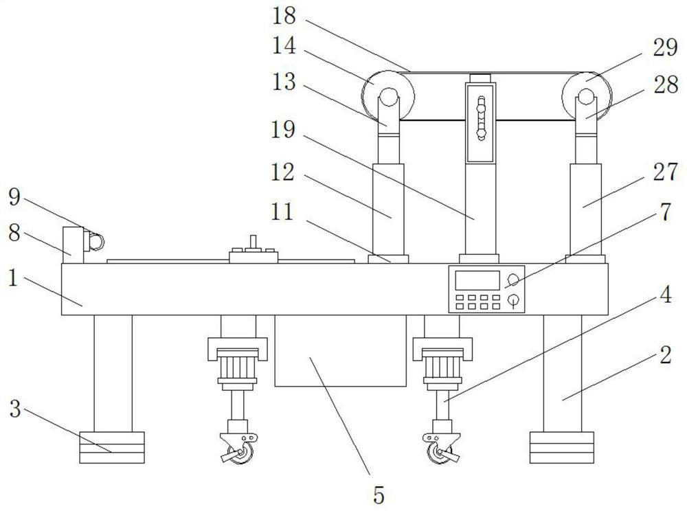
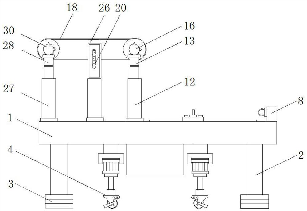
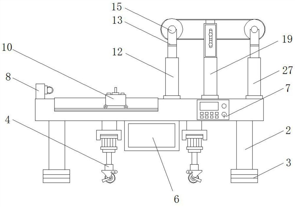
[0027] see Figure 1-7 , the present invention provides a composite cable testing tensile strength testing machine, such as figure 1 , image 3 , Figure 4 and Figure 5As shown, support legs 2 are provided on both sides of the bottom of the detection frame 1, and the bottom of the support legs 2 is fixedly connected with non-slip foot pads 3, and the moving mechanism 4 is arranged on both sides of the bottom of the detection frame 1, and a battery is arran...


PUM


Abstract

The invention discloses a tensile strength detection machine for testing a composite cable, which comprises a detection rack, a moving mechanism, a control panel, a tensile mechanism, a first fixed bracket, a first motor, a mounting frame, a first pulley, an extrusion plate, a telescopic cylinder, a second electric telescopic rod and a driven roller;supporting legs are arranged on the two sides of the lower portion of the detection rack. the moving mechanisms are arranged on the two sides of the bottom of the detection rack, the control panel is arranged on one side of the detection rack, the first motor is rotationally connected with the driving roller through the connecting shaft, the first pulley is arranged in the mounting frame, the extrusion plate is arranged below the second pulley, and one end of the telescopic air cylinder is fixedly connected with the mounting frame. According to the tensile strength detection machine for testing the composite cable, the tensile mechanism and the cable wear sensor are arranged, the strength of the composite cable can be conveniently detected through the tensile mechanism, the wear degree of the composite cable can be conveniently detected in real time through the cable wear sensor, and the service life of the composite cable can be conveniently mastered.

Description

technical field [0001] The invention relates to the technical field of composite cables, in particular to a tensile strength testing machine for composite cables. Background technique [0002] Cables are generally made of polypropylene as raw material through drawing, twisting, plying, braiding and other processes. This kind of cable has the advantages of soft texture, high strength and corrosion resistance. Cables are a necessity for connecting heavy objects in people's lives, so people attach great importance to the quality of cables. Some large-scale factories or scenic spots use cables, and the cables will be worn out if they are used continuously for a long time and under various load conditions. Over time, it may put the cable in a dangerous state. The existing composite cable testing tensile strength testing machine has a complex structure and is inconvenient to use, and the existing composite cable testing tensile strength testing machine has low practicability, an...

Claims


Application Information

Patent Timeline
Patent Type & Authority Applications(China)
IPC IPC(8): G01N3/02G01N3/10G01N3/56
CPCG01N3/02G01N3/10G01N3/56
Inventor 董红飞
Owner 盐城神力制绳有限公司
Learn More