Ship body and self-propelled three-body wave energy power generation platform

A wave energy, self-propelled technology, applied in the direction of ocean energy power generation, hull, hydrodynamic characteristics/hydrostatic characteristics, etc., can solve the problems of small deck area and cabin volume, high cost, and large influence of floats, etc., to achieve Good stability performance, large deck space, and the effect of increasing the deck area

Pending Publication Date: 2021-08-17
GUANGZHOU INST OF ENERGY CONVERSION - CHINESE ACAD OF SCI
View PDF0 Cites 0 Cited by
  • Summary
  • Abstract
  • Description
  • Claims
  • Application Information

AI Technical Summary

Problems solved by technology

This technical form requires multiple sets of lifting mechanisms, which are expensive, the float is greatly affected by the hull and the float, and the wave energy conversion efficiency is low
This technical form has small deck area and cabin capacity, limited production activities, and poor stability of the ship.

Method used


Image

  • Ship body and self-propelled three-body wave energy power generation platform
  • Ship body and self-propelled three-body wave energy power generation platform
  • Ship body and self-propelled three-body wave energy power generation platform

Examples


Embodiment 1

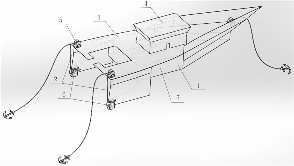
[0039] refer to figure 1As shown, the hull provided by this embodiment mainly includes a main body 1 , two auxiliary bodies 2 , a deck 3 , a superstructure 4 , three sets of mooring systems 5 , and two propellers 6 . Among them, the superstructure 4 is equipped with passenger cabin, cockpit, living facilities, etc., and the deck 3 connects the main body 1 and the auxiliary body 2, that is to say, the three bodies share a main deck and superstructure, which is similar to the monohull. It has the advantages of large deck space and good stability. The main body 1 is a buoyancy chamber, which mainly undertakes the task of wave energy conversion. Its volume is much larger than that of the two sides of the body. It is equipped with equipment 7 such as a power system and an energy storage system. The two auxiliary bodies 2 are small buoyancy chambers. The cabin has the same shape, and a propeller 6 is installed at the bottom, which are arranged in parallel on both sides of the rear ...

Embodiment 2

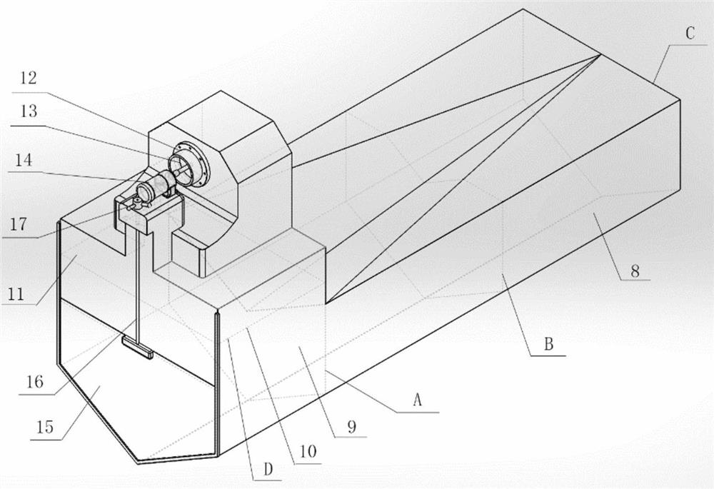
[0043] refer to Figure 2-4 As shown, the self-propelled three-body wave energy generation platform ( Figure 4 ) is mainly composed of the hull described in embodiment 1 ( figure 1 ) and the pneumatic wave energy generating device installed on the hull ( figure 2 ) composed of.

[0044] Such as figure 2 As shown, the pneumatic wave energy generating device includes a horizontal pipe 8 , a vertical cavity 9 , an air turbine 13 and a generator 14 .

[0045] Wherein, the vertical chamber 9 includes an oscillating water column 10, an air chamber 11 and an air hole 12; The upper part is contracted, and an air turbine 13 and a generator 14 are installed on the air inlet and outlet holes 12 .

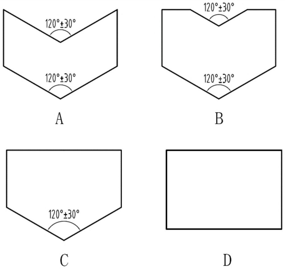
[0046] Such as figure 2 and 3 As shown, the length of the horizontal tube 8 is from figure 2 From the plane where the hexagon A is located to the plane where the pentagon C is located, the vertical section of the horizontal pipe 8 is a "concave" trumpet-shaped mouth, and a pentago...


PUM


Abstract

The invention discloses a ship body and a self-propelled three-body wave energy power generation platform. The ship body comprises a main sheet body, auxiliary sheet bodies and a deck, wherein the main sheet body is used as a buoyancy cavity; the auxiliary sheet bodies are used as auxiliary buoyancy cavities, and a propeller is mounted at the bottoms; the two auxiliary sheet bodies are oppositely installed on the two sides of the rear portion of the main sheet body in parallel; and the deck is used for connecting the main sheet body and the two auxiliary sheet bodies so that the ship body is formed among the four components. The ship body adopts the two auxiliary sheet bodies to install the propeller, the effect of the propeller can be exerted to the maximum efficiency, meanwhile, the two sheet bodies can compensate the unbalanced buoyancy of the main sheet body structure, the deck area can be increased, the space is expanded for production activity, the body amount of the middle sheet body is far larger than that of the sheet bodies on the two sides, and the middle sheet body is mainly used for carrying out a wave energy conversion task. The three sheet bodies share one main deck and an upper layer structure, and compared with a single wave energy power generation ship, the ship body is large in deck space and good in stability.

Description

technical field [0001] The invention relates to the technical field of wave power generation, in particular to a ship hull and a self-propelled three-body wave power generation platform. Background technique [0002] Wave energy resources are rich in reserves, widely distributed, and have great potential for development and utilization. Although there are many types of wave energy utilization technologies, the field is difficult, expensive, and the commercialization process is slow. [0003] There are many types of wave energy utilization technologies, and floating technology is the mainstream of development. Most of the floating technologies can be classified into three categories: oscillating water column technology, surfing technology and oscillating buoy technology. Floating and oscillating buoy technology uses waves to push one floating body relative to another floating body (supporting platform) to translate or rotate to convert energy. It is the mainstream of curren...

Claims


Application Information

Patent Timeline
IPC IPC(8): B63H19/02B63B1/12B63B35/44F03B13/14
CPCB63B1/125B63B35/44B63B2035/4466B63B2241/08B63H19/02F03B13/142F05B2220/706F05B2240/931F05B2240/95Y02E10/30Y02T70/5236
Inventor 吴必军张芙铭覃梓真
Owner GUANGZHOU INST OF ENERGY CONVERSION - CHINESE ACAD OF SCI
Why Eureka
Try Eureka