
Injection mold side edge deep barb demolding mechanism

A barb demoulding and injection mold technology, applied in the field of injection molds, can solve the problems of increasing the labor intensity of staff, reducing the efficiency of mold injection molding, and reducing the production efficiency of plastic products, so as to facilitate demoulding and injection work, and improve demoulding Efficiency, improve the effect of demoulding effect

Pending Publication Date: 2021-08-17
朱翠叶
View PDF0 Cites 1 Cited by
  • Summary
  • Abstract
  • Description
  • Claims
  • Application Information

AI Technical Summary

Problems solved by technology

However, with the continuous expansion and promotion of the application fields of plastic products, there are still some deficiencies in the actual production process of injection molds that need to be improved urgently.
[0003] In the prior art, due to the existence of the deep barbs on the side of the injection mold, the mold cannot normally perform one-time demoulding work, which reduces the injection molding efficiency of the mold. At the same time, in order to ensure the integrity of the plastic product barbs, it is often necessary to The staff spend a certain amount of time and energy adjusting the position of the core-pulling block at the barb, which increases the labor intensity of the staff and reduces the production efficiency of plastic products

Method used


Image

  • Injection mold side edge deep barb demolding mechanism
  • Injection mold side edge deep barb demolding mechanism
  • Injection mold side edge deep barb demolding mechanism

Examples


Embodiment Construction

[0029] The following examples are for illustrative purposes only and are not intended to limit the scope of the invention.

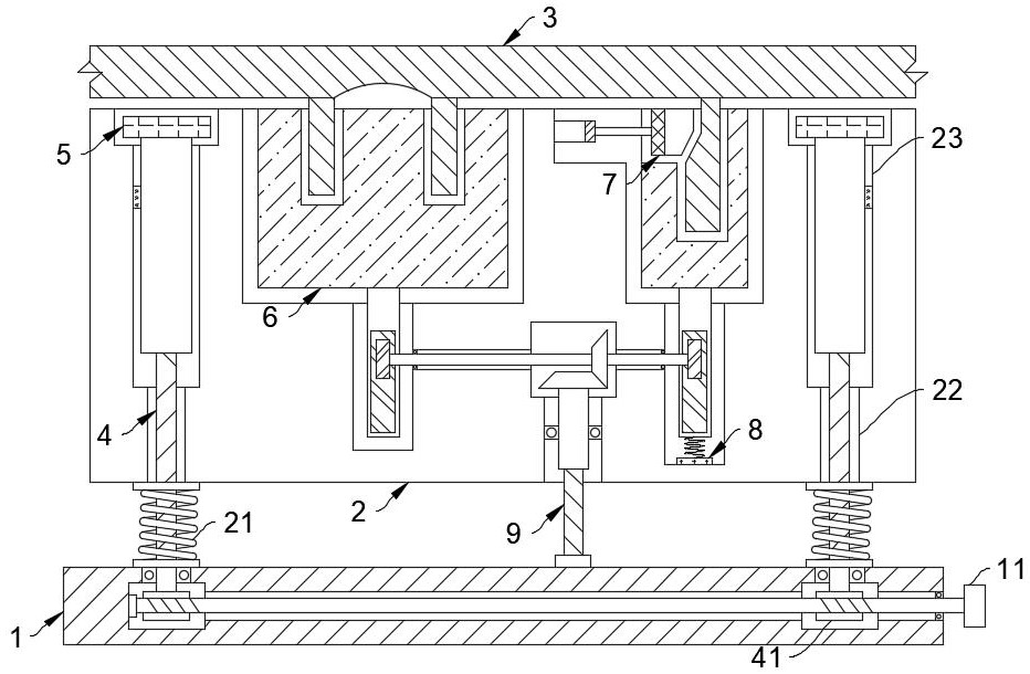
[0030] Such as Figure 1-5 As shown, a deep barb demoulding mechanism on the side of an injection mold includes a base 1, the base 1 is movably connected with a lower mold base 2, and the lower mold base 2 assists the upper mold base to perform mold closing and injection molding on the deep barb mold 3, It should be noted that the present invention adopts the upper mold base to fix the lower mold base 2 to carry out mold clamping and demoulding work, so as to improve the production and processing efficiency of the deep barb mold 3 .

[0031] The base 1 is rotatably connected with a support rod 4. It should be noted that the base 1 is rotatably connected with a drive rod 11, and the drive rod 11 and the support rod 4 are both rotatably connected to the base 1 through a bearing, and the drive rod 11 is rotated by a driving device such as a motor. Both end...


PUM


Abstract

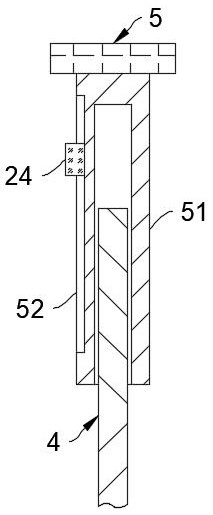
The invention belongs to the technical field of injection molds, and particularly relates to an injection mold side edge deep barb demolding mechanism. The mechanism comprises a base, the base is movably connected with a lower mold base, the lower mold base assists an upper mold base to conduct mold closing injection molding work on a deep barb mold, the base is rotationally connected with a supporting rod, one end of the supporting rod is in threaded connection with the lower mold base to realize mold closing and demolding work of the lower mold base and the upper mold base, the other end of the supporting rod is in threaded connection with a top plate, and the top plate performs ejection demolding work on the deep barb mold through the supporting rod. By arranging the supporting rod with two-way threads, demolding of the upper mold base and the lower mold base and ejection demolding of the deep barb mold can be conducted at the same time in the demolding process of a mold, a transmission mechanism can eject out a core pulling block in the demolding process of the lower mold base, the demolding effect of the deep barb mold is improved, the core pulling block can pull a ceramic electric sheet in the ejection process, so that a movable block is magnetically absorbed back, and the demolding work of the deep barb mold is facilitated.

Description

technical field [0001] The invention belongs to the technical field of injection molds, in particular to a deep barb release mechanism on the side of an injection mold. Background technique [0002] Injection molding, also known as injection molding, is a molding method of injection and molding. The advantages of the injection molding method are fast production speed, high efficiency, automatic operation, various designs and colors, simple to complex shapes, large to small sizes, accurate product sizes, easy replacement of products, and complex shapes. Parts, injection molding is suitable for mass production and complex shape products and other molding processing fields. However, with the continuous expansion and promotion of the application fields of plastic products, there are still some deficiencies in the actual production process of injection molds that need to be improved urgently. [0003] In the prior art, due to the existence of the deep barbs on the side of the i...

Claims


Application Information

Patent Timeline
IPC IPC(8): B29C45/40B29C45/33B29C45/44
CPCB29C45/332B29C45/401B29C45/44B29C2045/4042
Inventor 朱翠叶
Owner 朱翠叶
Learn More