
A cooling device for dispatching machine room

A heat dissipation device and computer room technology, which is applied in household heating, household heating, applications, etc., can solve the problems of poor heat dissipation and low energy efficiency ratio of cooling air conditioners in computer rooms, and achieve accurate heat dissipation, easy maintenance, and good support Effect

Active Publication Date: 2021-09-28
国网山东省电力公司昌邑市供电公司 +2
View PDF9 Cites 0 Cited by
  • Summary
  • Abstract
  • Description
  • Claims
  • Application Information

AI Technical Summary

Problems solved by technology

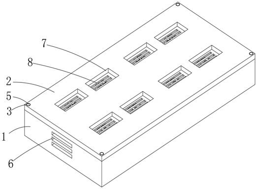
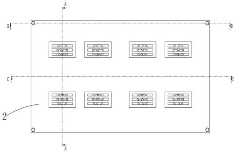
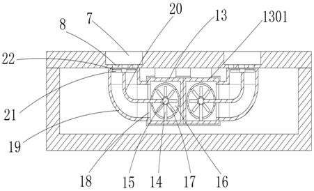
[0003] The invention provides a heat dissipation device for a dispatching machine room, which solves the problems of low heat dissipation energy efficiency ratio and poor heat dissipation effect of a heat dissipation air conditioner in a machine room in the prior art by setting a cooling fan, a heat dissipation pipe and a heat dissipation branch pipe

Method used


Image

  • A cooling device for dispatching machine room
  • A cooling device for dispatching machine room
  • A cooling device for dispatching machine room

Examples


Embodiment Construction

[0025] The present invention will be described in further detail below in conjunction with specific examples. It should be understood that the specific embodiments described here are only used to explain the present invention, not to limit the present invention.

[0026] In describing the present invention, it should be understood that the terms "center", "longitudinal", "transverse", "upper", "lower", "front", "rear", "left", "right", " The orientations or positional relationships indicated by "vertical", "horizontal", "top", "bottom", "inner" and "outer" are based on the orientations or positional relationships shown in the drawings, and are only for the convenience of describing the present invention and Simplified descriptions, rather than indicating or implying that the device or element referred to must have a particular orientation, be constructed and operate in a particular orientation, and thus should not be construed as limiting the invention.

[0027] In the descri...


PUM


Abstract

The invention discloses a heat dissipation device for a dispatching machine room, comprising a heat dissipation base and a top plate, the top plate is located on the upper surface of the heat dissipation base, heat dissipation grooves are arranged on opposite sides of the heat dissipation base, The opposite inner surface of the seat is equipped with a mounting seat, and the inside of the mounting seat is provided with a diversion groove, and the diversion groove is connected with the heat dissipation groove, and the inside of the diversion groove is provided with a mounting plate, and the mounting plate is installed There is a cooling fan, the mounting seat is connected with a first heat dissipation pipe and a second heat dissipation pipe, and the second heat dissipation pipe and the first heat dissipation pipe are symmetrically arranged on the center line of the mounting seat; the cooling fan is turned on, and the cooling fan passes through the first heat dissipation The tube and the second cooling tube perform heat absorption operation, and the heat is exported from the diversion groove and the heat dissipation groove; the energy efficiency ratio of heat dissipation is improved, and the heat dissipation efficiency is high.

Description

technical field [0001] The invention relates to the technical field of cooling in a computer room, in particular to a cooling device for a dispatching computer room. Background technique [0002] The dispatching computer room includes systems such as dispatch monitoring, state estimation, online load forecasting, automatic power generation control, and automatic economic dispatch. The dispatching computer room is an important part of the power system computer room. However, due to the large number of equipment in the dispatching computer room, air conditioning is routinely used for heat dissipation, but The power consumption of the air conditioner is too large, and it cannot directly dissipate heat to the equipment that needs to be cooled. The energy efficiency ratio of heat dissipation is too low, and the heat dissipation effect is poor; Contents of the invention [0003] The invention provides a heat dissipation device for a dispatching machine room, which solves the pro...

Claims


Application Information

Patent Timeline
Patent Type & Authority Patents(China)
IPC IPC(8): F24F5/00F24F13/30
CPCF24F5/0007F24F13/30
Inventor 张琪刘华建刘沛岩王冰徐广伟田超王强娄雪峰李焕超徐锦辉李玉国武海涛文雅刚刘立党
Owner 国网山东省电力公司昌邑市供电公司
Learn More