Multi-angle adjustable digging machine for ore mining
An excavator and multi-angle technology, which is applied in the directions of earth-moving drilling, slitting machinery, propulsion, etc., can solve the problems of single excavation angle, hidden dangers, inconvenient ore collection, etc., so as to improve mining efficiency, increase distance, and facilitate mining. effect of ore
- Summary
- Abstract
- Description
- Claims
- Application Information
AI Technical Summary
Problems solved by technology
Method used
Image
Examples
Embodiment 1
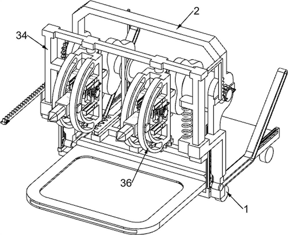
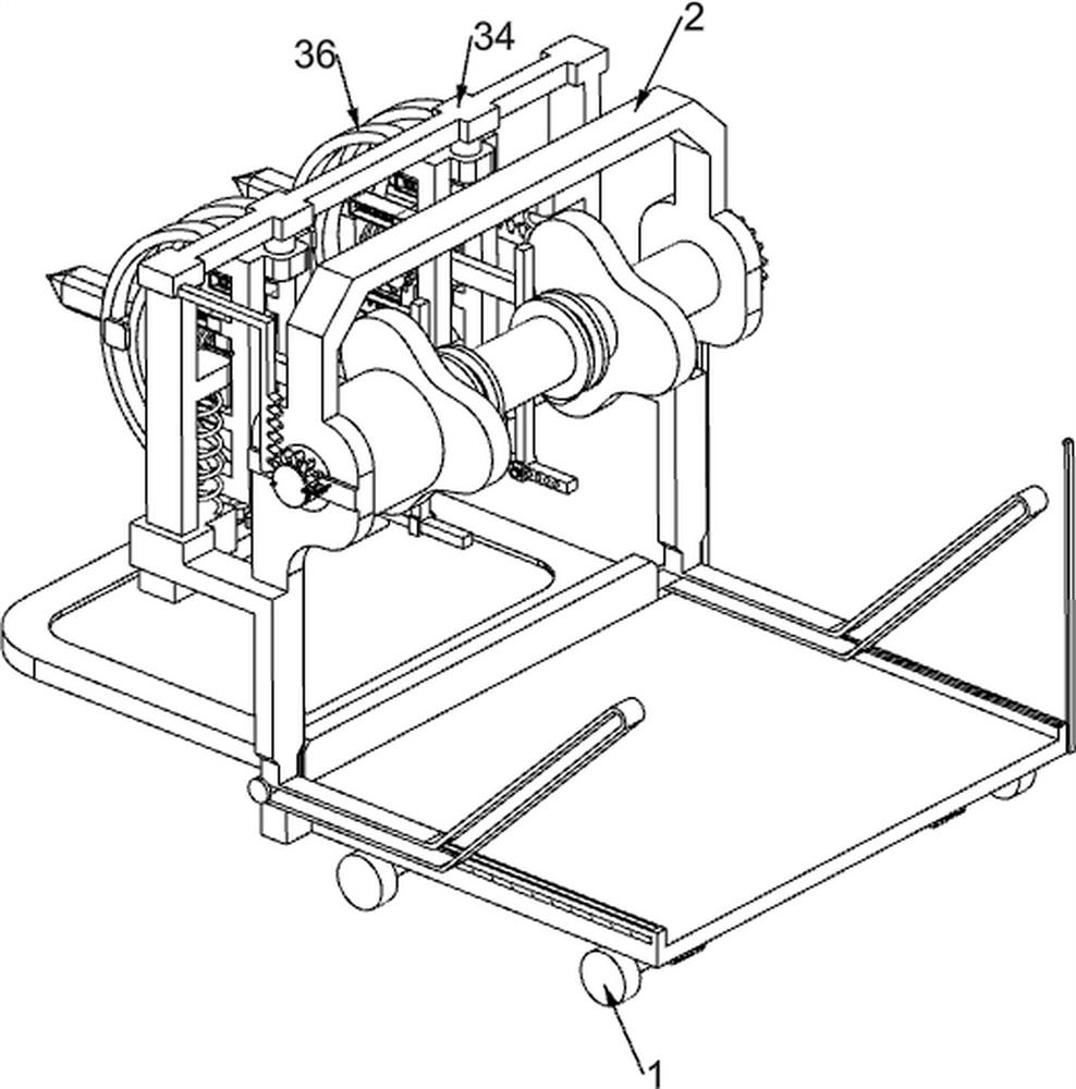
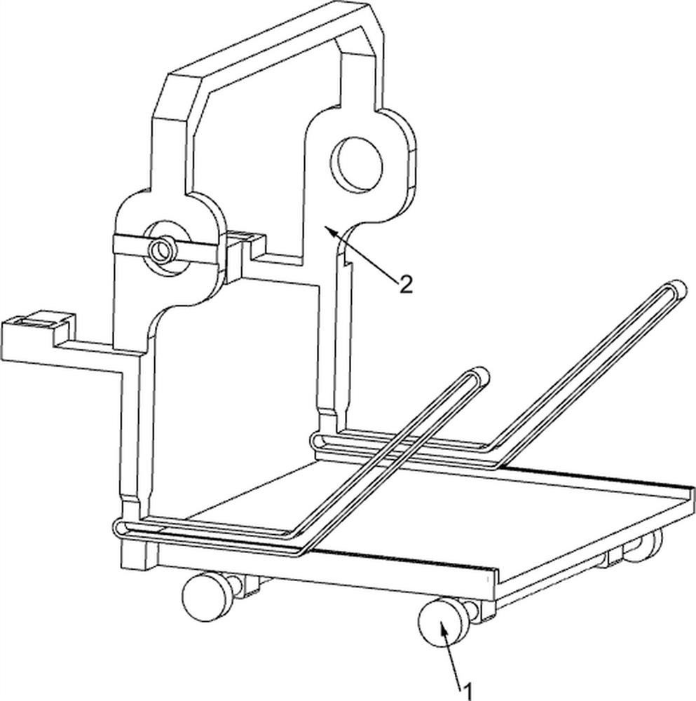
[0036] An excavator that can be adjusted at multiple angles for ore mining, such as Figure 1-7 As shown, it includes a wheeled underframe 1, a special-shaped opening chute frame 2, a driving mechanism 3 and a mining mechanism 4. Below the wheeled underframe 1 is a four-roller structure, and the four rollers are distributed in a rectangular shape. The wheeled underframe 1 The top is fixedly connected with a special-shaped perforated chute frame 2, and the special-shaped perforated chute frame 2 is provided with a drive mechanism 3 for providing power for the equipment, and the drive mechanism 3 is provided with a mining mechanism 4 for digging ore.
[0037] The driving mechanism 3 includes a servo motor 31, a transmission shaft 32, a triangular wheel 33, a slotted sliding frame 34, a first return spring 35, an arc adjustment frame 36, a slotted push frame 361 and a second return spring 37, and the special-shaped opening The upper right side of the chute frame 2 is fixedly inst...
Embodiment 2
[0041] On the basis of Example 1, such as Figure 7 As shown, an angle adjustment mechanism 5 is also included, and the angle adjustment mechanism 5 for adjusting the angle of the chisel head 42 is arranged on the slotting push frame 361. The angle adjustment mechanism 5 includes an adjustment shaft 51, a dial wheel 52, and a screw mandrel 53 , sliding nut block 54, the 4th back-moving spring 55, Z-shaped slotted frame 56, push wedge block 57 and the 5th back-moving spring 58, on the grooved pushing frame 361, the rotary type is connected with adjusting shaft 51, adjusting shaft 51 and chisel head 42 is fixedly connected, the left and right sides of the adjustment shaft 51 are fixedly connected with screw rods 53, one end of the screw rod 53 is fixedly welded with a dial wheel 52, and the dial wheel 52 is distributed with round rods in the circumferential direction, the number of which is at least 8, Slotted push frame 361 is connected with sliding nut block 54 in a symmetrica...
Embodiment 3
[0044] On the basis of Example 2, such as Figure 8-9 As shown, it also includes a swing adjustment mechanism 6, which is used to make the chisel head 42 excavate the mine with more angles. The swing adjustment mechanism 6 is located on the slotted sliding frame 34. One 62, the perforated rack frame 63, the sixth return spring 64, the perforated slide bar 65, the limit round bar 66 and the seventh return spring 67, a pair of cams 61 are fixedly connected on the transmission shaft 32, and the cam 61 below is convex. Block structure, the lower part of the bump is an arc surface structure, the two cams 61 are located between the two triangular wheels 33, and the gear one 62 is fixedly connected to the bottom of the arc adjustment frame 36, and the two gears one 62 are set correspondingly, sliding on the slotted sliding frame 34 A pair of perforated rack racks 63 are connected in the same way, and the two perforated rack racks 63 are located between the two gears one 62. One side ...
PUM
 Abstract
Description
Claims
Application Information
 - Generate Ideas
- Intellectual Property
- Life Sciences
- Materials
- Tech Scout
- Unparalleled Data Quality
- Higher Quality Content
- 60% Fewer Hallucinations
Browse by: Latest US Patents, China's latest patents, Technical Efficacy Thesaurus, Application Domain, Technology Topic, Popular Technical Reports.
© 2025 PatSnap. All rights reserved.Legal|Privacy policy|Modern Slavery Act Transparency Statement|Sitemap|About US| Contact US: help@patsnap.com


