
Textile fabric conveying device based on intermittent tensioning and vibration drainage drying structure

A conveying device and textile cloth technology, which is applied in the processing of textile materials, processing textile material drums, processing textile material carriers, etc., can solve the problem of not having a vibration drainage structure, not having an automatic conduction structure, not having tensioning and dehydrating components, etc. problems, to achieve good results in favor of drying and dehydration

Active Publication Date: 2021-08-13
江苏盈彩纺织科技有限公司
View PDF5 Cites 2 Cited by
  • Summary
  • Abstract
  • Description
  • Claims
  • Application Information

AI Technical Summary

Problems solved by technology

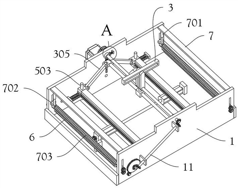
[0009] The object of the present invention is to provide a textile cloth conveying device based on intermittent tensioning and vibration drainage and drying structure, to solve the first problem proposed in the above-mentioned background technology, the conveying device currently used does not have an automatic intermittent tensioning mechanism, and does not have a corresponding The tensioning and dehydrating components of the existing fabric cannot quickly dehydrate the fabric; second, it does not have an automatic conduction structure that differentiates the conveying and tensioning steps, and cannot separate the conveying of the fabric through the automation of mechanical components; third, it does not have Corresponding vibration drainage structure problems

Method used


Image

  • Textile fabric conveying device based on intermittent tensioning and vibration drainage drying structure
  • Textile fabric conveying device based on intermittent tensioning and vibration drainage drying structure
  • Textile fabric conveying device based on intermittent tensioning and vibration drainage drying structure

Examples


Embodiment Construction

[0051] The following will clearly and completely describe the technical solutions in the embodiments of the present invention with reference to the accompanying drawings in the embodiments of the present invention. Obviously, the described embodiments are only some, not all, embodiments of the present invention.

[0052] In the description of the present invention, unless otherwise stated, the meaning of "plurality" is two or more; the terms "upper", "lower", "left", "right", "inner", "outer" , "front end", "rear end", "head", "tail", etc. indicate the orientation or positional relationship based on the orientation or positional relationship shown in the drawings, and are only for the convenience of describing the present invention and simplifying the description, rather than Nothing indicating or implying that a referenced device or element must have a particular orientation, be constructed, and operate in a particular orientation should therefore not be construed as limiting ...


PUM


Abstract

The invention discloses a textile fabric conveying device based on an intermittent tensioning and vibration drainage drying structure, and relates to the technical field of textile processing. The problem that a currently used conveying device is not provided with an automatic intermittent tensioning mechanism and a corresponding tensioning and dewatering assembly and cannot rapidly dewater fabric is solved. The textile fabric conveying device based on the intermittent tensioning and vibration drainage drying structure comprises two sets of main shell plates, two sets of lower assembly plates which are fixedly connected are arranged on the front sides and the rear sides of the bottoms of the two sets of main shell plates, and the adjacent positions of the bottoms of the lower set plates are arranged to be of a slope structure; an upper housing is fixedly arranged at the top of each main shell plate, and two sets of dryers are arranged at the top of each upper housing; and strip-shaped holes are formed in the two sides of the lower assembly plates. A dryer, a crankshaft, a strip-shaped frame and a fixing plate are arranged, an automatic intermittent tensioning mechanism and a corresponding tensioning and dewatering assembly are provided for the conveying device, and the automatic rapid dewatering function can be achieved.

Description

technical field [0001] The invention relates to the technical field of textile processing, in particular to a textile cloth conveying device based on an intermittent tensioning and vibration drainage and drying structure. Background technique [0002] Cloth is a commonly used material in decorative materials. During the processing of the cloth, it needs to be cleaned and then dehydrated to complete the processing and transportation. Generally, the drying structure is installed at the outlet of the washing machine for rapid drying to realize the transportation and processing of the cloth. [0003] After retrieval, for example, the patent No. CN111348462A discloses a textile cloth conveying device, including a conveyor, one side of the conveyor is provided with a winding roller, and the conveyor includes a driving conveying roller, a driven conveying roller, a conveying belt and a conveying frame, A plurality of fixing components are arranged at equal intervals on the conveyor...

Claims


Application Information

Patent Timeline
IPC IPC(8): D06B23/04D06B23/02D06B15/00D06B15/06
CPCD06B15/00D06B15/06D06B23/023D06B23/026D06B23/04
Inventor 黄美娟
Owner 江苏盈彩纺织科技有限公司
Learn More