Test tube storage device with good leakproofness for gastroenterology department
A gastroenterology, storage device technology, applied in unloading devices, packaging, rigid containers, etc., can solve problems such as damage and test tubes are prone to collision, and achieve the effect of preventing mutual collisions
- Summary
- Abstract
- Description
- Claims
- Application Information
AI Technical Summary
Problems solved by technology
Method used
Image
Examples
Embodiment 1
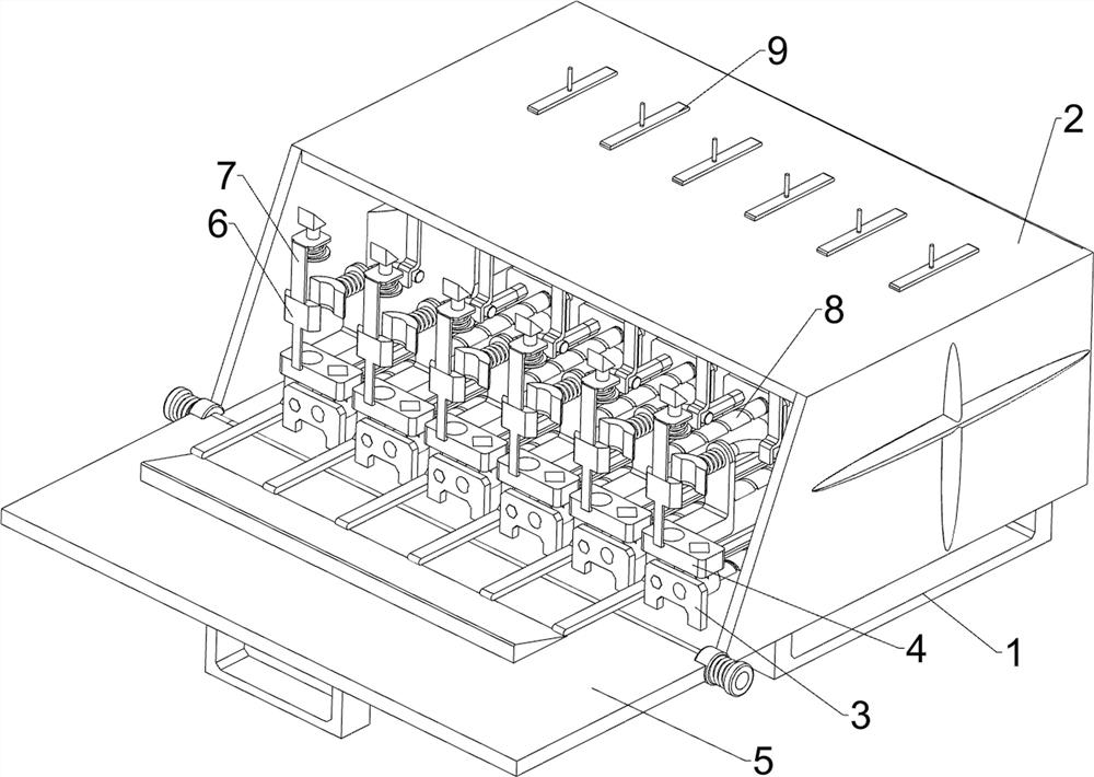
[0030] A test tube storage device for gastroenterology with good airtightness, such as Figure 1-2 As shown, it includes a base 1, a housing 2, a fixed plate 3, a storage mechanism 4 and a cover mechanism 5, the left and right sides of the bottom of the housing 2 are connected with the base 1, and the front and rear sides of the inner bottom of the housing 2 are connected with There are a plurality of fixed plates 3 , a storage mechanism 4 is installed between the fixed plates 3 , and a cover mechanism 5 is installed on the front side of the housing 2 .
[0031] The storage mechanism 4 includes a placement plate 41, a first rhombic rod 42 and a constant temperature lamp 43, the first rhombus rod 42 is connected between the front and rear two fixed plates 3, and the outer wall of the first rhombus rod 42 is slidingly connected to the placement plate 41, The inner walls of the left and right sides of the casing 2 are connected with constant temperature lamps 43 .
[0032] The c...
Embodiment 2
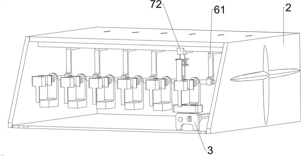
[0035] On the basis of Example 1, such as figure 1 , image 3 and Figure 4 As shown, a clamping mechanism 6 is also included, and the clamping mechanism 6 includes a connecting plate 61, a first clamping plate 62, a first guide plate 63, an L-shaped bar 64, a second clamping plate 65 and a first return spring 66, and the housing 2 The front side of the inner top is connected with a plurality of connecting plates 61 evenly spaced, the front side of the placing plate 41 is connected with the first splint 62, the rear side of the placing plate 41 is connected with the first guide plate 63, and the upper part of the first guide plate 63 is slidably connected with a L Shaped bar 64, L-shaped bar 64 cooperates with connecting plate 61, and L-shaped bar 64 front ends are connected with second clamping plate 65, and second clamping plate 65 cooperates with first clamping plate 62, is connected between second clamping plate 65 and first guide plate 63 The first return spring 66 .
...
Embodiment 3
[0038] On the basis of Example 2, such as figure 1 , image 3 and Figure 4As shown, a blocking mechanism 7 is also included, and the blocking mechanism 7 includes a second guide plate 71, a wedge block 72, a cover 73 and a second return spring 74, the top of the first splint 62 is connected with the second guide plate 71, and the top of the second guide plate 71 A wedge block 72 is slidably connected, and the wedge block 72 cooperates with the housing 2 . A cover 73 is connected to the bottom of the wedge block 72 , and a second return spring 74 is connected between the cover 73 and the second guide plate 71 .
[0039] The backward movement of the first splint 62 can drive the second guide plate 71 to move backward, and the backward movement of the second guide plate 71 drives the parts on it to move backward. When the wedge block 72 moves backward to contact with the housing 2, the Under the action of the body 2, the wedge-shaped block 72 can be moved downward, and the wed...
PUM
 Abstract
Description
Claims
Application Information
 - Generate Ideas
- Intellectual Property
- Life Sciences
- Materials
- Tech Scout
- Unparalleled Data Quality
- Higher Quality Content
- 60% Fewer Hallucinations
Browse by: Latest US Patents, China's latest patents, Technical Efficacy Thesaurus, Application Domain, Technology Topic, Popular Technical Reports.
© 2025 PatSnap. All rights reserved.Legal|Privacy policy|Modern Slavery Act Transparency Statement|Sitemap|About US| Contact US: help@patsnap.com


