
Magnetic buffering type anti-collision beam at front end of automobile

A technology of anti-collision beams and magnetic force, which is applied to vehicle components, vehicle safety arrangements, bumpers, etc., can solve problems such as difficult to flexibly adjust the collision buffer force, high cost of use, deformation of the main beam, etc., to improve the effect of buffering energy absorption, good cushioning effect

Inactive Publication Date: 2021-08-13
郑娜
View PDF0 Cites 0 Cited by
  • Summary
  • Abstract
  • Description
  • Claims
  • Application Information

AI Technical Summary

Problems solved by technology

[0004] In view of this, the purpose of this disclosure is to propose a magnetic buffer type anti-collision beam at the front end of a car to solve the problem that after a collision, the main beam and the energy-absorbing box are easily deformed and damaged, especially in low-speed collisions, which often cause The main beam is deformed and needs to be replaced as a whole, the cost of use is high, and the buffering force of the collision is difficult to adjust flexibly

Method used


Image

  • Magnetic buffering type anti-collision beam at front end of automobile
  • Magnetic buffering type anti-collision beam at front end of automobile
  • Magnetic buffering type anti-collision beam at front end of automobile

Examples


Embodiment Construction

[0029] In order to make the purpose, technical solutions and advantages of the present disclosure clearer, the present disclosure will be further described in detail below in conjunction with specific embodiments.

[0030] It should be noted that, unless otherwise defined, the technical terms or scientific terms used in the embodiments of the present disclosure shall have ordinary meanings understood by those skilled in the art to which the present disclosure belongs. "First", "second" and similar words used in the embodiments of the present disclosure do not indicate any sequence, quantity or importance, but are only used to distinguish different components. "Comprising" or "comprising" and similar words mean that the elements or items appearing before the word include the elements or items listed after the word and their equivalents, without excluding other elements or items. Words such as "connected" or "connected" are not limited to physical or mechanical connections, but ...


PUM


Abstract

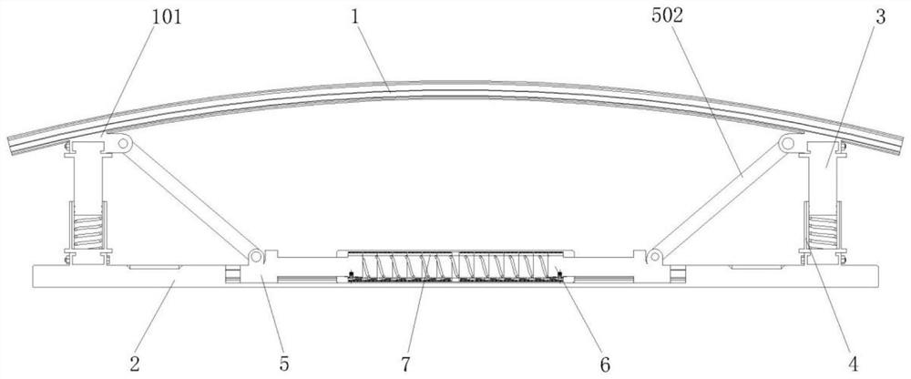
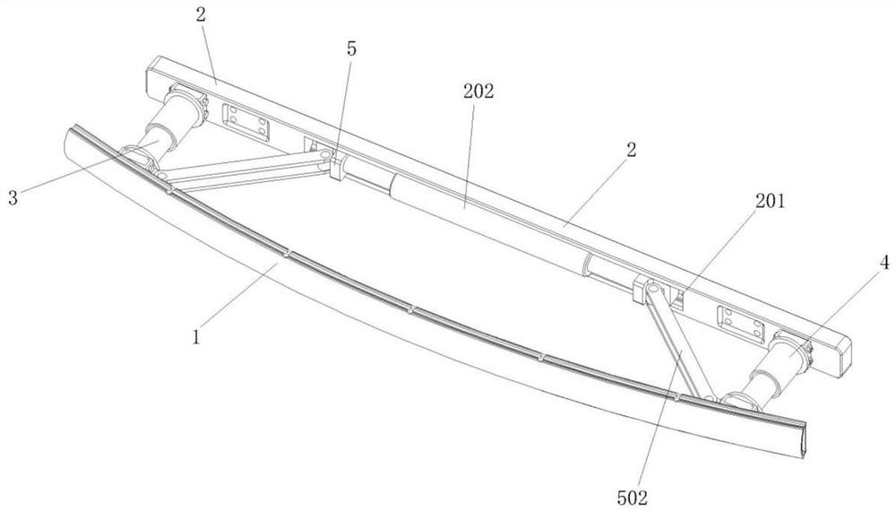
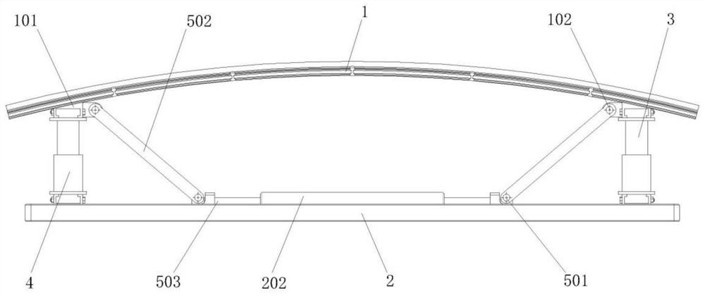
The invention provides a magnetic buffering type anti-collision beam at the front end of an automobile. The anti-collision beam comprises a bow-shaped main beam the back surface of which are provided with connecting clamping bases symmetrically on the left side and the right side, with connecting rotating shafts being arranged in the middles of the connecting clamping bases; a horizontal fixing frame arranged on the rear side of the bow-shaped main beam in parallel; and a telescopic guide rod arranged on the rear side of the connecting clamping bases, a circular sliding block is arranged at the rear end of the telescopic guide rod, and a permanent magnet blocking ring is arranged in the middle of the circular sliding block in a surrounding mode. According to the anti-collision beam, the bow-shaped main beam serves as the collision main beam and is fixed to an automobile through the horizontal fixing frame, the bow-shaped main beam and the horizontal fixing frame are connected through the telescopic guide rod and a telescopic guide cylinder, and the bow-shaped main beam can move towards the rear side to enable the telescopic guide rod and the telescopic guide cylinder to slide relatively when collided, then thepermanent magnet blocking ring is driven to slide in a magnetic resistance inner copper tube, and the telescopic guide rod is hindered through electromagnetic resistance generated by a buffer spring and relative sliding of the buffer spring, so that buffering and energy absorption are carried out.

Description

technical field [0001] The present disclosure relates to the technical field of automobile anti-collision beams, in particular to an automobile front-end magnetic buffer type anti-collision beam. Background technique [0002] The car anti-collision beam is a device used to reduce the absorption of collision energy when the vehicle is hit by a collision. It is composed of a main beam, an energy-absorbing box, and a mounting plate connected to the car. The energy-absorbing box is then connected to the longitudinal beam of the vehicle body in the form of bolts. Both the main beam and the energy-absorbing box can effectively absorb the collision energy when the vehicle collides at a low speed, and minimize the damage of the impact force to the longitudinal beam of the vehicle body. It can protect the vehicle, and the anti-collision beam structure should ensure that the low-speed energy-absorbing box can effectively absorb the energy of low-speed impact through collapse. The anti...

Claims


Application Information

Patent Timeline
Patent Type & Authority Applications(China)
IPC IPC(8): B60R19/02B60R19/24B60R19/36
CPCB60R19/023B60R19/24B60R19/36B60R2019/026
Inventor 郑娜
Owner 郑娜
Learn More