
Construction bin system for large metal 3D printing equipment

A 3D printing and metal technology, applied in the field of building silo systems, it can solve the problems such as the inability to fully guarantee the consistency of the forming cylinder and the driving cylinder, the inaccurate alignment between the forming cylinder and the printing warehouse, and the offset, so as to achieve precise connection and eliminate position deviation. The effect of shifting and reducing the error rate

Active Publication Date: 2021-08-13
JIHUA LAB
View PDF6 Cites 0 Cited by
  • Summary
  • Abstract
  • Description
  • Claims
  • Application Information

AI Technical Summary

Problems solved by technology

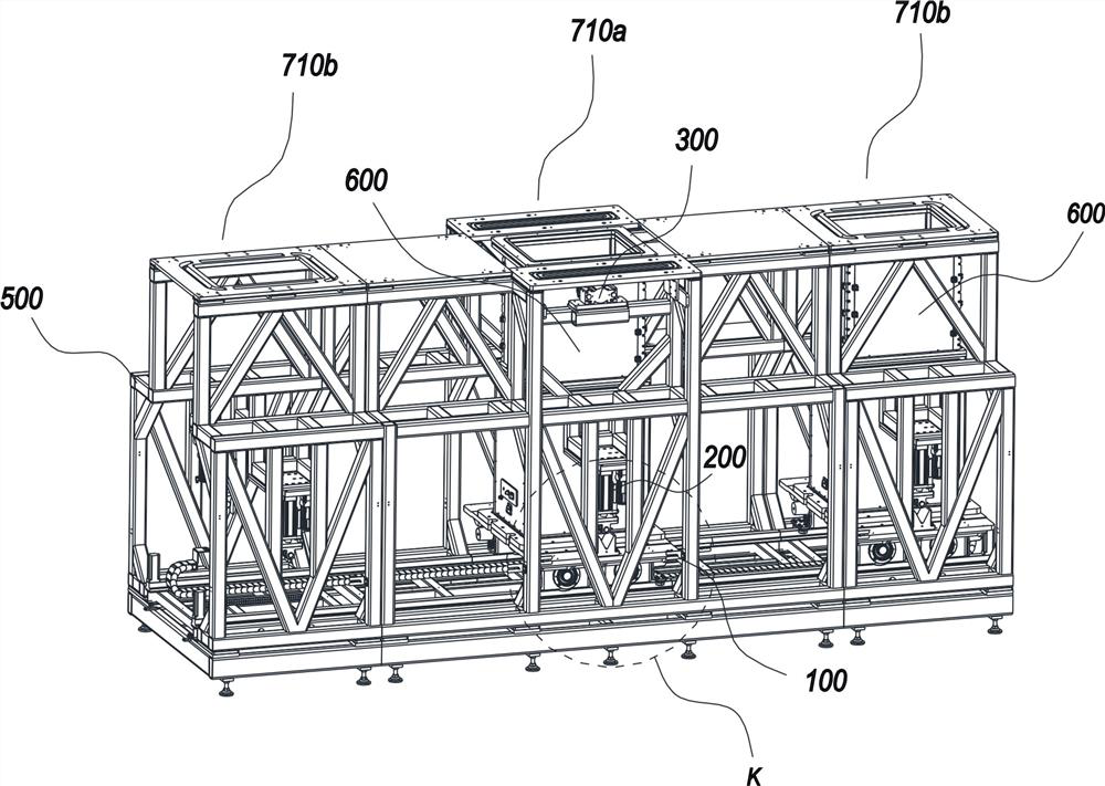
However, in order to achieve a good printing work, it is also necessary to consider the precise positioning of the building chamber during the moving process. Due to the split connection between the forming cylinder and the driving cylinder, and the large size of the building chamber for large workpieces, during the moving process Due to shaking and other factors, the position of the upper forming cylinder may be slightly shifted relative to the driving cylinder, which may lead to inaccurate alignment between the upper forming cylinder and the printing chamber even though the positioning of the building chamber is completed at the specified position. , it is impossible to fully guarantee that the forming cylinder and the driving cylinder are exactly the same in the fixed point position

Method used


Image

  • Construction bin system for large metal 3D printing equipment
  • Construction bin system for large metal 3D printing equipment
  • Construction bin system for large metal 3D printing equipment

Examples


Embodiment Construction

[0033] Embodiments of the present invention are described in detail below, examples of which are shown in the drawings, wherein the same or similar reference numerals denote the same or similar elements or elements having the same or similar functions throughout. The embodiments described below by referring to the figures are exemplary only for explaining the present invention and should not be construed as limiting the present invention.

[0034]In describing the present invention, it should be understood that the terms "center", "longitudinal", "transverse", "length", "width", "thickness", "upper", "lower", "front", " Orientation indicated by rear, left, right, vertical, horizontal, top, bottom, inside, outside, clockwise, counterclockwise, etc. The positional relationship is based on the orientation or positional relationship shown in the drawings, which is only for the convenience of describing the present invention and simplifying the description, rather than indicating o...


PUM


Abstract

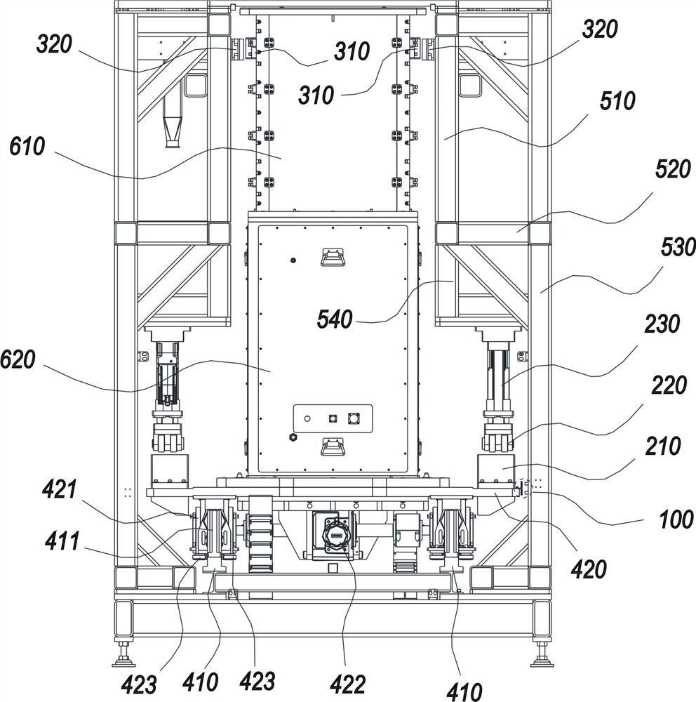
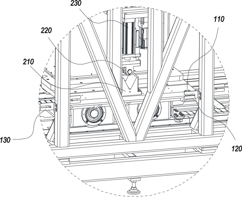
The invention discloses a construction bin system for large metal 3D printing equipment. The construction bin system comprises a positioning mechanism. The positioning mechanism comprises an initial positioning assembly, a first positioning mechanism, a second positioning mechanism and a controller. The initial positioning assembly is arranged between a corresponding working station and a construction bin and is used for detecting whether the construction bin reaches the corresponding working station or not. The first positioning mechanism is arranged between the corresponding working station and a driving cylinder. The second positioning mechanism is arranged between the corresponding working station and a forming cylinder. The first positioning mechanism is used for positioning the construction bin at the lower part of the construction bin, and the second positioning mechanism is used for positioning the construction bin at the upper part of the construction bin The controller is used for controlling the construction bin to stop moving when the initial positioning assembly detects that the construction bin reaches the corresponding working station, controlling the first positioning mechanism to act and controlling the second positioning mechanism to act after the first positioning mechanism completes positioning of the construction bin. According to the construction bin system for the large metal 3D printing equipment, accurate positioning of the construction bin in the moving process can be achieved.

Description

technical field [0001] The invention belongs to the technical field of 3D printing equipment, and in particular relates to a building chamber system for large-scale metal 3D printing equipment. Background technique [0002] In the 3D printing equipment using selective melting technology, the equipment mainly includes the upper printing chamber and the lower construction chamber. The printing work is carried out in the airtight construction chamber. After the printing is completed, the workpiece needs to be taken out from the construction chamber and processed. Powder cleaning, which requires downtime for processing. [0003] In recent years, with the maturity of 3D printing technology, the size of printed workpieces has become larger and larger. R&D personnel in the industry have set their sights on metal 3D printing of large workpieces. Since the removal of the workpiece and the powder cleaning need to be shut down, the utilization rate of the equipment and the printing ef...

Claims


Application Information

Patent Timeline
Patent Type & Authority Applications(China)
IPC IPC(8): B22F12/80B22F10/31B22F10/28B22F12/90B33Y30/00B33Y50/02
CPCB33Y30/00B33Y50/02
Inventor 王冠博李建杰何刚文赵豪侯志轩
Owner JIHUA LAB
Learn More