Protection mechanism of bending machine

A protection mechanism and bending machine technology, applied in metal processing equipment, safety equipment, manufacturing tools, etc., can solve problems such as insufficient safety, staff injury, and metal material fracture, so as to improve safety protection performance and protection safety , the effect of reducing personal injury

Active Publication Date: 2021-08-13
江苏克莱德激光技术有限责任公司
View PDF10 Cites 2 Cited by
  • Summary
  • Abstract
  • Description
  • Claims
  • Application Information

AI Technical Summary

Problems solved by technology

[0002] A bending machine is a machine that can bend metal materials such as metal plates and steel bars. It can process metal materials into their own shapes according to requirements. However, some existing bending machines have problems with insufficient safety. 1) Use When the bending machine bends the metal material, the bending force is large, which will cause the metal material to break. Due to improper protection, the splash of debris generated after the break will cause injury to the staff; 2) The metal material located outside the bending machine Reversal occurs during bending, and the staff will be injured by metal materials when they are close to the bending machine; 3) Sometimes staff improperly use their hands in the work area, which will cause major personal injury accidents during bending

Method used


Image

  • Protection mechanism of bending machine
  • Protection mechanism of bending machine
  • Protection mechanism of bending machine

Examples


Embodiment Construction

[0027] The following is a clear and complete description of the technical solutions in the implementation of the present invention in conjunction with the accompanying drawings, and the described embodiments are only part of the embodiments of the present invention, not all of them. Based on the embodiments of the present invention, all other embodiments obtained by persons of ordinary skill in the art without making creative efforts fall within the protection scope of the present invention.

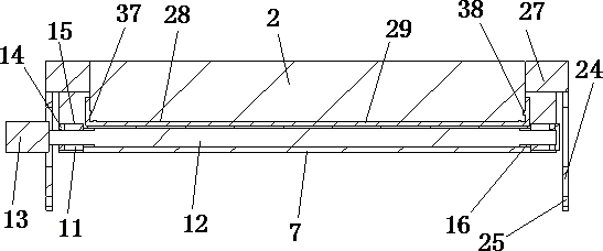
[0028] Such as Figure 1 to Figure 7As shown, a protective mechanism of a bending machine provided by the embodiment of the present invention, the bending machine includes a bending machine top box 1, a bending machine bottom box 2, a lifting plate 3, an upper pressing plate 4, a fixed table 5 and a lower pressing plate 6. The protective mechanism is installed on the top box 1 of the bending machine and the bottom box 2 of the bending machine and is located on the side of the fixed table...


PUM


Abstract

The invention discloses a protection mechanism of a bending machine, and belongs to the technical field of metal material bending processing equipment. The protection mechanism is mounted on a bending machine top box and a bending machine bottom box and positioned at one side, far away from the bending machine, of a fixed table; the protection mechanism comprises a protection curtain, a roller shutter assembly, a telescopic assembly, a rotation driving assembly, an upper fixing block and a lower fixing block, wherein one end of the protection curtain is installed on the telescopic assembly, the other end of the protection curtain is installed on a roller shutter, and the protection curtain is retracted and wound through the roller shutter assembly or stretched through the telescopic assembly; and the roller shutter assembly is rotationally installed on the upper fixing block, the telescopic assembly is fixedly installed on the rotation driving assembly, the rotation driving assembly is rotationally installed on the lower fixing block, and the telescopic assembly is driven by the rotation driving assembly to rotate. According to the protection mechanism, a metal material machining area is shielded, so that personnel injury accidents caused during metal material machining are effectively avoided, and the safety performance of the bending machine is improved.

Description

technical field [0001] The invention relates to a protection mechanism of a bending machine, which belongs to the technical field of metal material bending processing equipment. Background technique [0002] A bending machine is a machine that can bend metal materials such as metal plates and steel bars. It can process metal materials into their own shapes according to requirements. However, some existing bending machines have problems with insufficient safety. 1) Use When the bending machine bends the metal material, the bending force is large, which will cause the metal material to break. Due to improper protection, the splash of debris generated after the break will cause injury to the staff; 2) The metal material located outside the bending machine Reversal occurs during bending, and workers will be injured by metal materials when they are close to the bending machine; 3) Sometimes workers put their hands in the work area improperly, which will cause major personal injur...

Claims


Application Information

Patent Timeline
IPC IPC(8): B21D55/00
CPCB21D55/00
Inventor 李玲风车朝杰
Owner 江苏克莱德激光技术有限责任公司
Why Eureka
Try Eureka