Variable multi-point unloader

An unloader, multi-point technology, applied in the conveyor control device, cleaning device, conveyor and other directions, to achieve the effect of convenient operation, simple structure and less space occupied

Pending Publication Date: 2021-08-10
吴凤丽
View PDF0 Cites 0 Cited by
  • Summary
  • Abstract
  • Description
  • Claims
  • Application Information

AI Technical Summary

Problems solved by technology

[0006] The beneficial effect of adopting the above-mentioned technical scheme is: the feeding method is to receive the upstream material from the tail feeding ship and feed the material along the direction of the belt conveyor tail to the head conveying direction, and add multiple variants and multiple points in the middle of all belt conveyors according to the needs of the user unit The unloader solves the problem of improving efficiency and material crushing in the field of grain transportation. The modified multi-point unloader is suitable for various environments. The indoor and outdoor exposure ensures that there will be no contact with rain or dust overflow during unloading and bring it to the head. Gray belt phenomenon, simple structure and convenient operation, the transmission bearings are all outside the shell, convenient for refueling and maintenance, due to the double-roller lifting structure, it takes up less space than the same unloader, and there are no wearing parts to reduce labor

Method used


Image

  • Variable multi-point unloader
  • Variable multi-point unloader
  • Variable multi-point unloader

Examples


Embodiment Construction

[0029] The present invention will be further described below in conjunction with accompanying drawing.

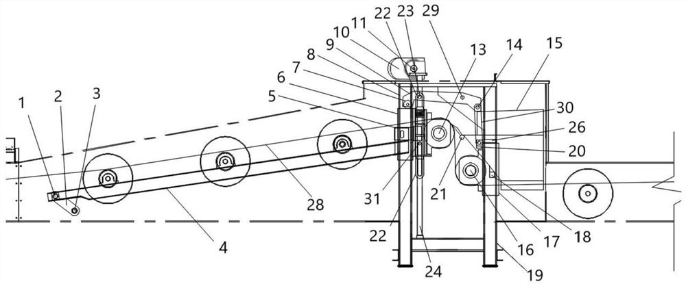
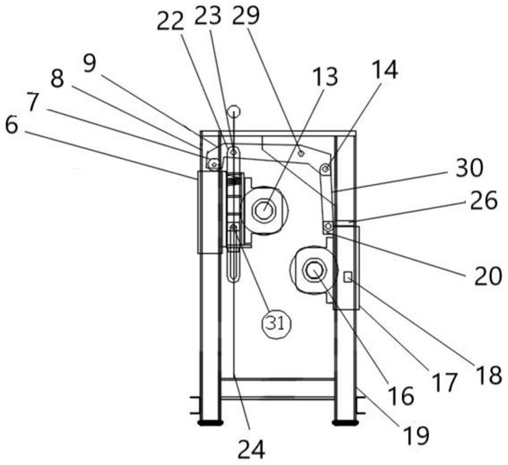
[0030] Such as figure 1 , figure 2 with image 3 As shown, a modified multi-point unloader of the present invention includes a row bar 4, a belt 28, a first lifting drum 13, a second lifting drum 16 and a motor 10; the belt is carried on a deep groove installed on the row bar 4 type idler, the first lifting roller 13 and the second lifting roller 16; the fixed end of the row bar 4 is connected on the frame, and the vertical lifting end of the row bar 4 is connected with the lifting lug 5 on the first sliding sleeve 6; The first lifting roller 13 is fixed on the first sliding sleeve 6; the motor 10 controls the first lifting roller 13 to rise or fall through the screw 24; the second lifting roller 16 is fixed on the second sliding sleeve 17, the second The upper end of the sliding sleeve 17 has a second lifting lug 20 connected to the lower end of the lifting link 30, th...


PUM


Abstract

The invention discloses a variable multi-point unloader, comprising a row bar, a belt, a first lifting roller, a second lifting roller and a motor. The belt is borne by a deep groove type carrier roller, a first lifting roller and a second lifting roller which are mounted on the row bar. The first lifting roller moves upwards, the upper end surface of a first sliding sleeve touches a rotating bearing to drive a thrust lever to press a lifting connecting rod downwards, and the second lifting roller is driven to move downwards, so that a height difference of the belt is formed between the first lifting roller and the second lifting roller; the first lifting roller moves downwards, a fixed shaft pin on the first sliding sleeve moves downwards in a sliding groove of an ascending connecting rod to the bottom end of the sliding groove to pull the ascending connecting rod to move downwards, the thrust lever is driven to press downwards to drive the lifting connecting rod to move upwards, and the second lifting roller is towed by the lifting connecting rod to move, so that the height difference of the belt between the first lifting roller and the second lifting roller is recovered. The unloader improves the efficiency and the crushing problem, is suitable for various indoor and outdoor environments, occupies a small space, and is convenient to maintain.

Description

technical field [0001] The invention relates to a grain logistics storage and conveying device, in particular to a modified multi-point unloader. Background technique [0002] The advantage of the existing plow unloader is that the equipment is compact and occupies a small space, and the maize is better without leakage. The coulter is wear-resistant, and its disadvantage is that the materials that cannot be unloaded are wheat, rice, rapeseed, etc. The reason is that the rice is worn and the coulter is particularly fast to cause leakage. The material causes the rice husk to fall off and become brown rice, which is not easy to store and carry the material to the head. Wheat and coulters are severely worn, causing material to leak to the head. The rapeseed and coulter are severely worn, and the rapeseed is squeezed out. It is easy to clean the material on the head. The maintenance cost is high and unsafe. The maintenance personnel have to enter the equipment. The cover rubber o...

Claims


Application Information

Patent Timeline
Patent Type & Authority Applications(China)
IPC IPC(8): B65G47/44B65G47/22B65G21/14B65G15/60B65G39/12B65G45/12B65G43/00
CPCB65G15/60B65G21/14B65G39/12B65G43/00B65G45/12B65G47/22B65G47/44
Inventor 刘育森王军胡居成张梦华洪思亮
Owner 吴凤丽
Why Eureka
Try Eureka