
Thighbone far-end inner side bone fracture plate

A bone plate and distal technology, applied in the field of medical devices, can solve the problems of iatrogenic injury, insufficient support, and high technical requirements

Inactive Publication Date: 2021-08-10
SHANGHAI EAST HOSPITAL EAST HOSPITAL TONGJI UNIV SCHOOL OF MEDICINE
View PDF0 Cites 0 Cited by
  • Summary
  • Abstract
  • Description
  • Claims
  • Application Information

AI Technical Summary

Problems solved by technology

[0003] For simple distal femoral fractures, simple distal femoral lateral locking plate fixation can be used to obtain better clinical results; however, for A3, C2, and C3 distal femoral fractures, which are complex fractures, most of them are fixed by high-energy fractures. It is one of the most difficult fractures to treat due to injury. If only lateral plate fixation is used, it often faces high complications (such as poor union, nonunion, delayed union)
At this time, it is often necessary to use double bone plate treatment (one plate for the outer and inner sides of the distal femur). At present, the bone plate for the medial distal femur is mostly replaced by the distal tibial plate or the tibial plateau bone plate, or a reconstructed bone plate. The three kinds of bone plates are not as good as the distal femoral lateral bone plate in terms of screw diameter and bone plate thickness alone, and the screw diameter is small, the holding force is insufficient, the bone plate is thin, and the support strength is not enough
Therefore, even if many fractures are fixed with double bone plates, the final treatment effect is not ideal.
At the same time, the non-anatomical bone plate is placed on the inner side of the distal femur, which requires repeated shaping to fit the inner side of the distal femur, which is difficult and requires high technical skills for the surgeon, which will increase the operation time
[0004] At present, although a small number of manufacturers have launched medial distal femoral bone plates, they still face the above-mentioned problems of small screw diameters or thin bone plates
At the same time, there are a large number of blood vessels and nerves on the inner side of the distal femur. If the bone plate is not anatomical or the shape is too poor to fit the bone surface, it is easy to cause irritation to the surrounding nerves and blood vessels, and even iatrogenic damage
Moreover, if a longer bone plate is selected, incorrect placement techniques often cause the proximal end of the bone plate to warp, making it impossible to place screws

Method used


Image

  • Thighbone far-end inner side bone fracture plate
  • Thighbone far-end inner side bone fracture plate
  • Thighbone far-end inner side bone fracture plate

Examples


Embodiment 1

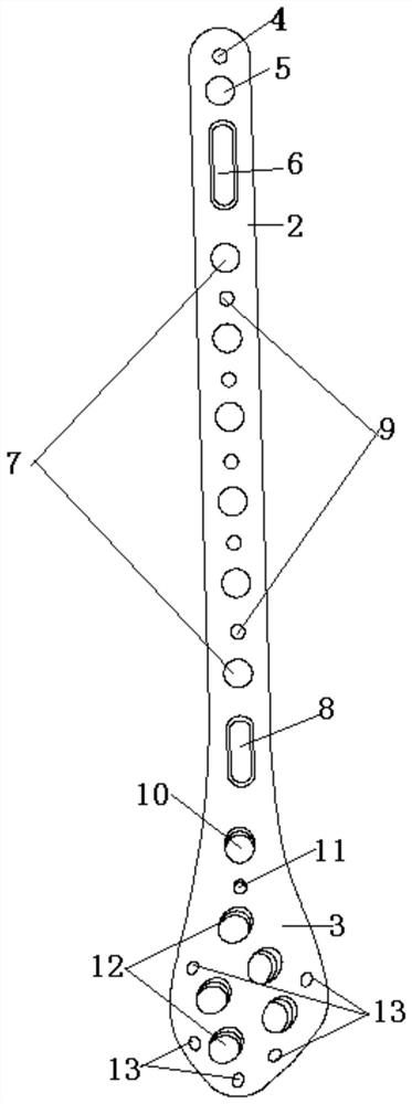
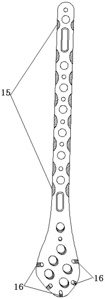
[0020] like Figure 1-Figure 3 The shown bone plate on the inner side of the distal end of the femur includes a bone plate body 1, the thickness of the bone plate body 1 is 0.4-0.6cm, the length is 9-25cm, and the width is 1.3-3.0cm. The bone plate body 1 Divided into a proximal section 2 and a distal section 3, the distal section 3 gradually thins and extends from top to bottom to both sides, bends inward, and has an arc-shaped structure, and the arc is 25° from the vertical line, which is the same as the vertical line. The contour of the lateral condyle of the distal end of the femur is fitted, and the proximal section 2 is curved to a certain arc, which is the same as the arc of the anterior femoral arch. The proximal end section 2 is provided with a proximal upper K-wire hole 4, a proximal upper locking hole 5, a sliding hole 6, a proximal lower locking hole 7 and a sliding hole I8 in sequence from top to bottom. The proximal lower locking hole 7 There are a plurality of ...

Embodiment 2

[0022] like Figure 1-Figure 3 The shown bone plate on the inner side of the distal end of the femur includes a bone plate body 1, the thickness of the bone plate body 1 is 0.4-0.6cm, the length is 9-25cm, and the width is 1.3-3.0cm. The bone plate body 1 Divided into a proximal section 2 and a distal section 3, the distal section 3 gradually thins and extends from top to bottom to both sides, from 4-6mm to 3.0mm at the most distal end, and bends inward in an arc. The radian is 25° from the vertical line, and fits with the contour of the outer condyle of the distal femur. The proximal section 2 is curved to a certain radian, which is the same as the radian of the anterior arch of the femur, which is convenient for the bone plate body 1 to fit. The proximal end section 2 and the distal end section 3 are connected smoothly and in an integrated structure. The proximal end section 2 has a proximal upper K-wire hole 4, a proximal upper locking hole 5, and a sliding hole 6 in sequen...


PUM

PropertyMeasurementUnit
Thicknessaaaaaaaaaa
Lengthaaaaaaaaaa
Widthaaaaaaaaaa

Abstract

The invention discloses a thighbone far-end inner side bone fracture plate which comprises a bone fracture plate body, the bone fracture plate body is divided into a near-end section and a far-end section, the far-end section is gradually thinned and extends towards the two sides from top to bottom in the width direction and is bent inwards, the near-end section is bent by a certain radian, the near-end section is sequentially provided with a near-end upper kirschner wire hole, near-end upper locking holes, a sliding hole, near-end lower locking holes and a sliding hole I from top to bottom, there are multiple near-end lower locking holes, and near-end lower kirschner wire holes are formed between the adjacent near-end lower locking holes. The far-end section is provided with far-end upper locking holes, far-end upper kirschner wire holes and far-end lower locking holes from top to bottom, there are multiple the far-end lower locking holes, and a plurality of far-end lower kirschner wire holes are formed in the peripheries of the far-end lower locking holes. The device is specially designed according to the anatomical characteristics of the inner side of the femur and the anterior inner side of the femur, the device is more attached to the bone surface, the fixing strength is guaranteed, meanwhile, less soft tissue is peeled off and irritated, and the medial collateral ligament of the knee joint is not affected.

Description

technical field [0001] The invention relates to the technical field of medical devices, in particular to a bone plate for the inner side of the distal end of the femur. Background technique [0002] Due to the complex anatomical structure of the medial distal femur, involving the femoral artery, femoral vein, sciatic nerve, tibial nerve, and common peroneal nerve, medial incision can easily lead to iatrogenic injury. The medial distal femoral plate is mainly divided into two ways: combined use and independent use. Except for the limited skin conditions of the lateral femur, most of the distal femoral plate is combined with the medial plate. [0003] For simple distal femoral fractures, simple distal femoral lateral locking plate fixation is often used, which can achieve better clinical results; however, for A3, C2, and C3 distal femoral fractures, they are complex fractures, which are mostly caused by high-energy Injury is one of the most difficult fractures to treat. If a ...

Claims


Application Information

Patent Timeline
IPC IPC(8): A61B17/80
CPCA61B17/8061A61B17/808
Inventor 刘立峰方楠彭青武乐高硕
Owner SHANGHAI EAST HOSPITAL EAST HOSPITAL TONGJI UNIV SCHOOL OF MEDICINE
Learn More