Pipe irrigation type drought control system and working method thereof

A technology for drought prevention and tube irrigation, which is applied in botanical equipment and methods, watering devices, gardening, etc., can solve the problems of interval irrigation, high labor costs, waste of water resources, etc., to reduce water and solve high labor costs. , reduce the effect of breeding

Active Publication Date: 2021-08-10
JIANGSU DONGZHU LANDSCAPE CONSTR
View PDF6 Cites 0 Cited by
  • Summary
  • Abstract
  • Description
  • Claims
  • Application Information

AI Technical Summary

Problems solved by technology

[0007] Purpose of the invention: In order to overcome the above deficiencies, the purpose of the invention is to provide a pipe-irrigated drought prevention system and its working method. On the one hand, it adopts buried, mechanical irrigation and electric control irrigation to solve the problem of high labor cost and waste of water resources. , Irrigation has intervals, unsightly, etc. It has strong protection ability for vegetation and low cost. On the other hand, it adopts a modular structure, which is convenient for maintenance
[0009] The setting of the drought prevention system described in the present invention adopts ground burial, mechanical irrigation and electric control irrigation, which solves the problems of high labor cost, waste of water resources, intervals in irrigation, and unsightly appearance. It has strong protection ability for vegetation and low cost. Low

Method used


Image

  • Pipe irrigation type drought control system and working method thereof
  • Pipe irrigation type drought control system and working method thereof
  • Pipe irrigation type drought control system and working method thereof

Examples


Embodiment 1

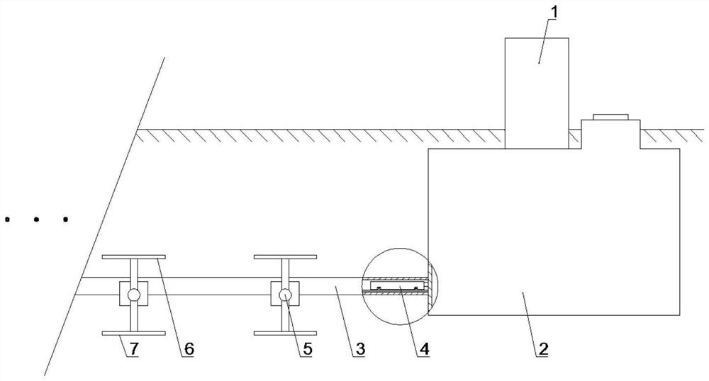
[0054] Such as Figure 1-6 A tube-irrigated drought prevention system shown includes: a control cabinet 1, a water tank 2, a delivery pipeline 3, a conveyor 4, a regulating pipe 5, an anti-evaporation cover plate 6 and an anti-loss support plate 7. The control cabinet 1 The bottom is provided with a water tank 2, the bottom of the water tank 2 is provided with a conveying pipe 3, one side of the conveying pipe 3 is connected with an adjusting pipe 5, and there are multiple regulating pipes 5, and the top of the regulating pipe 5 is provided with an anti- Evaporation cover plate 6, anti-loss support plate 7 is provided at the bottom of the regulating pipe 5; a conveyor 4 is provided in the conveying pipeline 3.

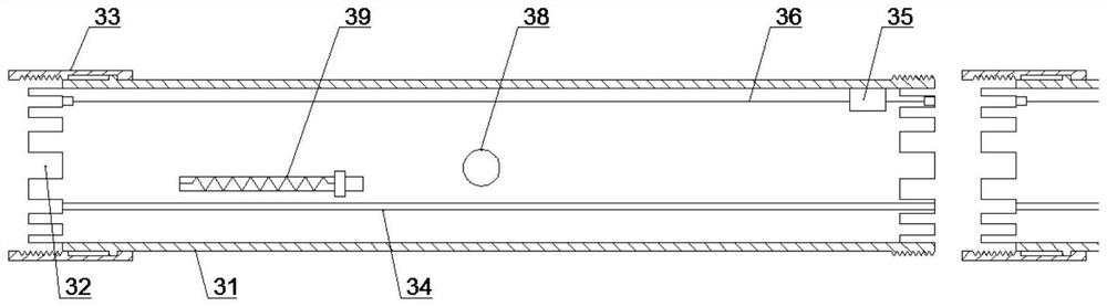
[0055] The conveying pipeline 3 described in this embodiment is provided with a plurality of, and the conveying pipeline 2 is connected in a queue, and the conveying pipeline 3 includes a pipe body 31, a fixing slot 32, a sealing threaded sleeve 33 and a feeding guide ...

Embodiment 2

[0071] Such as Figure 1-3 A tube-irrigated drought prevention system shown includes: a control cabinet 1, a water tank 2, a delivery pipeline 3, a conveyor 4, a regulating pipe 5, an anti-evaporation cover plate 6 and an anti-loss support plate 7. The control cabinet 1 The bottom is provided with a water tank 2, the bottom of the water tank 2 is provided with a conveying pipe 3, one side of the conveying pipe 3 is connected with an adjusting pipe 5, and there are multiple regulating pipes 5, and the top of the regulating pipe 5 is provided with an anti- Evaporation cover plate 6, anti-loss support plate 7 is provided at the bottom of the regulating pipe 5; a conveyor 4 is provided in the conveying pipeline 3.

[0072] The conveying pipeline 3 described in this embodiment is provided with a plurality of, and the conveying pipeline 2 is connected in a queue, and the conveying pipeline 3 includes a pipe body 31, a fixing slot 32, a sealing threaded sleeve 33 and a feeding guide ...

Embodiment 3

[0076] Such as figure 1 and 4 A tube-irrigated drought prevention system shown includes: a control cabinet 1, a water tank 2, a delivery pipeline 3, a conveyor 4, a regulating pipe 5, an anti-evaporation cover plate 6 and an anti-loss support plate 7. The control cabinet 1 The bottom is provided with a water tank 2, the bottom of the water tank 2 is provided with a conveying pipe 3, one side of the conveying pipe 3 is connected with an adjusting pipe 5, and there are multiple regulating pipes 5, and the top of the regulating pipe 5 is provided with an anti- Evaporation cover plate 6, anti-loss support plate 7 is provided at the bottom of the regulating pipe 5; a conveyor 4 is provided in the conveying pipeline 3.

[0077]The conveyor 4 described in this embodiment includes a bracket 41, a middle box 42, a water delivery jacket 43, a water delivery interface 44, a sealing valve 45, and a running wheel 46. The bracket 41 is provided with a middle box 42, and the middle One sid...


PUM


Abstract

The invention discloses a pipe irrigation type drought prevention system. The pipe irrigation type drought prevention system comprises a control cabinet, a water tank, a conveying pipeline, a conveyor, adjusting pipes, an evaporation prevention cover plate and a loss prevention supporting plate, the water tank is arranged at the bottom of the control cabinet, the conveying pipeline is arranged at the bottom of the water tank, one side of the conveying pipeline is connected with the multiple adjusting pipes, the evaporation prevention cover plate is arranged at the tops of the adjusting pipes, and the loss prevention supporting plate is arranged at the bottoms of the adjusting pipes; and a conveyor is arranged in the conveying pipeline. The invention further discloses a working method of the pipe irrigation type drought control system. On the one hand, buried, mechanical irrigation and electric control irrigation are adopted, the problems of high labor cost, water resource waste, interval irrigation, unattractiveness and the like are solved, the vegetation protection capability is high, and the cost is low; and on the other hand, the modular structure is adopted, and maintenance is convenient.

Description

technical field [0001] The invention belongs to the field of drought prevention devices and technologies, in particular to a pipe-irrigated drought prevention system and a working method thereof. Background technique [0002] In recent years, landscaping construction has been included in the social development plans of governments at all levels as an important infrastructure construction, and the importance of urban greening and regional greening has been recognized by everyone. However, in the relatively arid central and northern regions, landscaping has been greatly hindered. Due to the low local precipitation, in order to ensure the survival of the greening, it is necessary to arrange a lot of money, labor and equipment to irrigate and maintain the greening, and the maintenance cost is extremely high. . Therefore, a high-efficiency and convenient greening and drought prevention equipment that can reduce labor and cost is an urgent need for R&D personnel to solve. [000...

Claims


Application Information

Patent Timeline
IPC IPC(8): A01G25/02A01G25/16
CPCA01G25/023A01G25/167
Inventor 沈建军惠泓王永恒曹莎莎
Owner JIANGSU DONGZHU LANDSCAPE CONSTR
Why Eureka
Try Eureka