Road material detection device

A detection device and material technology, applied in the direction of sampling devices, etc., can solve the problems of affecting the results of road detection, poor sampling accuracy, and unstable devices, so as to achieve the convenience of promotion and use, increase the scope of use, and facilitate storage. Effect

Inactive Publication Date: 2021-08-06
重庆德飞科技有限责任公司
View PDF1 Cites 0 Cited by
  • Summary
  • Abstract
  • Description
  • Claims
  • Application Information

AI Technical Summary

Problems solved by technology

[0002] Urban road construction plays an important role in the existing urban construction system. In the later stage of road construction, samples of the road will be collected and the quality of the road will be inspected. For example, the patent with the publication number CN112268737A mainly through Drive the motor and drive the drill cylinder to sample the road. The cooperation of the two arc-shaped plates and the two springs improves the stability of the drill cylinder during the drilling process. However, the device is not stable enough during the sampling process in this way. As a result, the drill pipe is easy to tilt, resulting in poor sampling accuracy, which affects the results of road inspections

Method used


Image

  • Road material detection device
  • Road material detection device
  • Road material detection device

Examples


Embodiment 1

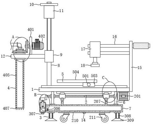
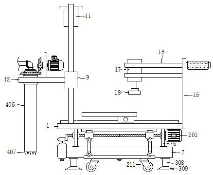
[0029] see Figure 1-7, the present invention provides a technical solution: a road material detection device, comprising a working board 1, a lifting mechanism 2 and a fixing mechanism 3 are arranged under the working board 1, a rotating mechanism 4 is arranged on one side of the working board 1, and the working board 1 is provided with a sliding mechanism 5, the bottom of the working plate 1 is fixedly installed with two groups of connecting plates 6, the bottom of the connecting plate 6 is fixedly installed with an installation box 7, and the top of the working plate 1 is fixedly installed with two groups of vertical rods 8 and is in the shape of Set front and rear, sliding block 9 is installed on the outer wall of vertical pole 8, and fixed plate 10 is fixedly installed on the adjacent side walls of two groups of vertical poles 8, and the bottom of fixed plate 10 is fixedly installed with first hydraulic rod 11, and the first hydraulic rod The free end of 11 is fixedly con...

Embodiment 2

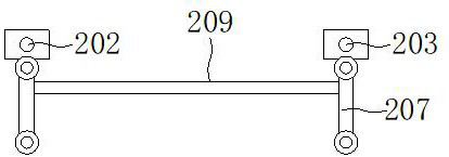
[0033] see Figure 1-7 , on the basis of Embodiment 1, the lifting mechanism 2 includes a first motor 201, a two-way threaded rod 202, a sliding rod 203, a first slide rail 204, a first sliding seat 205, a moving block 206, a hinged rod 207, a limit rod 209, the lifting plate 210 and the wheels 211, the first motor 201 is fixedly installed on one side of the outer wall of one of the connecting plates 6, the two ends of the two-way threaded rod 202 are respectively rotated and installed on the two sets of connecting plates 6, the first motor 201 is connected by transmission On the two-way threaded rod 202, the two ends of the sliding rod 203 are fixedly connected to two sets of connecting plates 6 respectively, and the first slide rail 204 is fixedly installed on the bottom of the working plate 1, and the number of the first slide rail 204 is two groups and is arranged front and back. , the number of first sliding seats 205 is four groups, wherein two first sliding seats 205 ar...


PUM


Abstract

The invention discloses a road material detection device, and relates to the technical field of road detection sampling. The road material detection device comprises a working plate, a lifting mechanism and a fixing mechanism are arranged below the working plate, a rotating mechanism is arranged on one side of the working plate, a sliding mechanism is arranged above the working plate, two sets of connecting plates are fixedly mounted at the bottom of the working plate, and mounting boxes are fixedly mounted at the bottoms of the connecting plates. According to the road material detection device, the device can be conveniently fixed, the stability of the device is improved, and the hollow drill cylinder is prevented from inclining when the device is used for sampling, so that the sampling accuracy is ensured, the accuracy of the subsequent detection result of a road sample is ensured, the device can be effectively prevented from shaking in the sampling process, and therefore, the service life of a road is prevented from being shortened due to cracks of a subgrade nearby sampling caused by shaking, the plasticity of the device is improved, and the device is convenient to popularize and use.

Description

technical field [0001] The invention relates to the technical field of road detection and sampling, in particular to a road material detection device. Background technique [0002] Urban road construction plays an important role in the existing urban construction system. In the later stage of road construction, samples of the road will be collected and the quality of the road will be inspected. For example, the patent with the publication number CN112268737A mainly through Drive the motor and drive the drill cylinder to sample the road. The cooperation of the two arc-shaped plates and the two springs improves the stability of the drill cylinder during the drilling process. However, the device is not stable enough during the sampling process in this way. As a result, the drill pipe is easy to tilt, resulting in poor sampling accuracy, which in turn affects the results of road testing. Contents of the invention [0003] The object of the present invention is to provide a ro...

Claims


Application Information

Patent Timeline
IPC IPC(8): G01N1/08
CPCG01N1/08
Inventor 王飞
Owner 重庆德飞科技有限责任公司
Why Eureka
Try Eureka