Building construction rainfall drainage structure

A drainage structure and building construction technology, which is applied to drainage structures, buildings, sewage discharge, etc., can solve the problems of blockage of the filter plate, inability to play a drainage role, and rise of the water level above the filter plate, so as to reduce the flow of the drainage pipe, good and effective Drainage work, the effect of stabilizing the position of the pump rod

Active Publication Date: 2021-08-06
NANJING RUNSHENG CONSTR GROUP
View PDF13 Cites 1 Cited by
  • Summary
  • Abstract
  • Description
  • Claims
  • Application Information

AI Technical Summary

Problems solved by technology

[0004] The above-mentioned documents can filter rainwater during the drainage process to prevent rainwater from carrying sundries and other pollutants into the sewer. However, in construction sites with a lot of sediment, when the rainfall is heavy, the accumulated water will bring the sediment to the top of the drainage structure , resulting in blockage of the filter plate, resulting in the rise of the water level above the filter plate, which cannot play a good drainage effect, and then cannot solve the problem of material soaking caused by the rise of the water level caused by heavy rainfall

Method used


Image

  • Building construction rainfall drainage structure
  • Building construction rainfall drainage structure
  • Building construction rainfall drainage structure

Examples


Embodiment

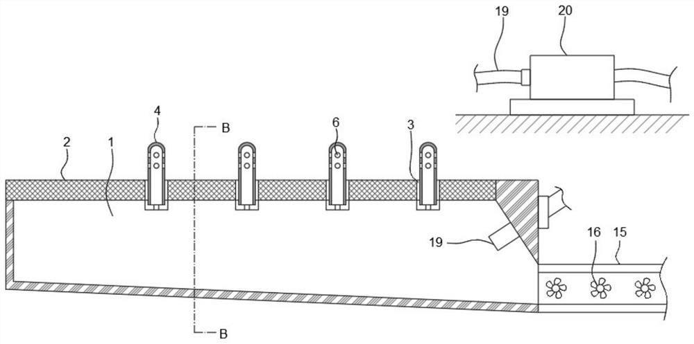
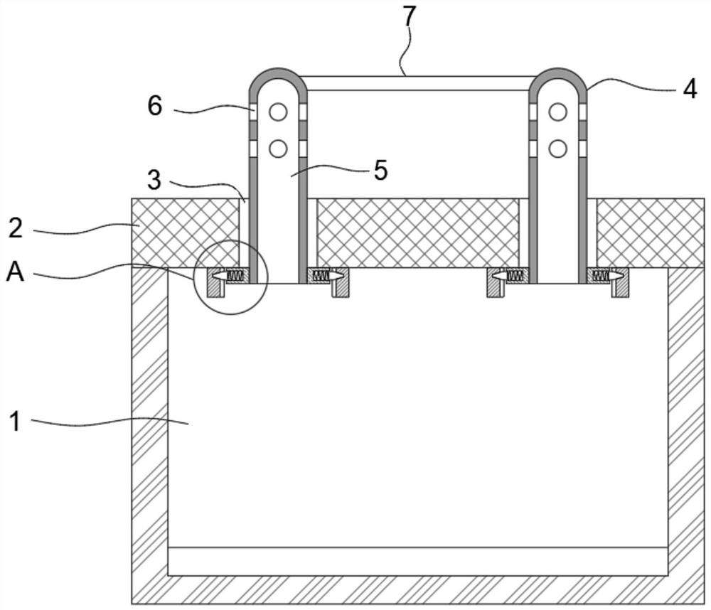
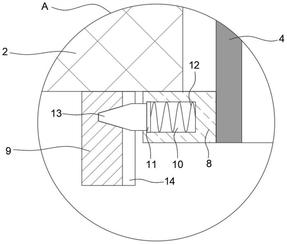
[0024] refer to Figure 1-4 , a building construction rainfall drainage structure, comprising a drainage channel 1, the upper end of the drainage channel 1 is provided with an opening, and the inner bottom wall of the drainage channel 1 is arranged downwardly from left to right, so that the rainwater flowing into the drainage channel 1 is convenient to the effect of its own gravity The bottom flows from left to right, and then flows to the drainage pipe 15. The upper end of the drainage channel 1 is sealed and fixedly connected with the seepage mesh plate 2, and the drainage channel 1 is buried under the ground so that the water seepage mesh plate 2 is kept parallel to the ground, and the water seepage mesh plate 2 can block Sediment, only let the rainwater infiltrate, and then ensure that the soil on the construction site will not be lost, and at the same time, the sediment in the drainage pipe 15 will not be caused to settle. A water pump 20 is arranged above the ground. Suc...


PUM


Abstract

The invention discloses a building construction rainfall drainage structure. The building construction rainfall drainage structure comprises a drainage channel, wherein the upper end of the drainage channel is open, the inner bottom wall of the drainage channel is obliquely arranged downwards from left to right, a water seepage net plate is fixedly connected to the upper end of the drainage channel in a sealed mode, two rows of circular insertion blocks which are symmetrical about the transverse axis of the water seepage screen plate are fixedly embedded in the upper end of the water seepage screen plate, a water pumping rod is vertically and movably inserted in each circular insertion block, the lower end of each water pumping rod extends into the drainage channel, a water suction cavity is formed in each water pumping rod, the lower end of each water suction cavity communicates with the drainage channel, a plurality of water inlets are formed in the peripheral surface of the upper end of each water pumping rod, and fixed blocks are fixedly connected to the front and rear positions of the end, which is located in the drainage channel, of each water pumping rod. The building construction rainfall drainage structure has the advantages that rainfall accumulated water of a construction site can be continuously and effectively drained, the structure adapts to different rainfall intensities and has the effects of energy conservation and environment friendliness, and the water level is prevented from rising.

Description

technical field [0001] The invention relates to the technical field of building construction, in particular to a rainwater drainage structure for building construction. Background technique [0002] In the construction site, due to the imperfect drainage system, when the rain occurs during the construction process, the rainwater cannot be discharged in time, which will cause the construction site to accumulate water, and then cause the building materials to be soaked and damaged for a long time, and the construction cannot be resumed in time. In order to resume construction in time, construction workers will set up drainage structures on the construction site to discharge rainwater in time. [0003] After searching, the public number CN211499114U provides a construction rainfall drainage structure, including a base plate and an upper filter plate, an upper filter plate is fixedly installed above the base plate, a slope is fixedly installed at the bottom of the base plate, an...

Claims


Application Information

Patent Timeline
IPC IPC(8): E03F1/00E03F3/04E03F5/14
CPCE03F1/00E03F3/046E03F5/14
Inventor 万青松万继生任辉辉许瑞姚鑫孙继宁芮航秦进陈聚亮
Owner NANJING RUNSHENG CONSTR GROUP
Why Eureka
Try Eureka