Buoy device, method for controlling buoy to fall down in time, water inlet valve and water drainage valve

A water inlet valve and floating control technology, applied in the field of sanitary ware, can solve the problems of buoyancy setting, the displacement exceeding the actual requirement, and the parts cannot move in time, etc., and achieve the effect of simple structure.

Pending Publication Date: 2021-08-06
JOMOO KITCHEN & BATHROOM
View PDF0 Cites 1 Cited by
  • Summary
  • Abstract
  • Description
  • Claims
  • Application Information

AI Technical Summary

Problems solved by technology

The above structure is usually as figure 1 As shown, the one-way switch 3' is a float, which rises under buoyancy in the water, and its upper surface is in close contact with the lower surface of the buoy seat 2' to form a seal, and water cannot enter from the drain at the bottom of the buoy seat 2'; the buoy seat 2' After the external water level drops to a certain level, the pressure generated by the difference in internal and external water levels is greater than the buoyancy of the one-way switch 3', the one-way switch 3' is turned on, and the water flows out from the hole at the bottom of the buoy seat 2', causing the buoy 1' to fall
[0003] However, the above-mentioned structure has the following problems. To make the pressure generated by the water level difference inside and outside the buoy seat be greater than the buoyancy of the one-way switch, the water level in the water tank must drop to a very low position. will fall
If the buoy does not fall, the components linked with it will not be able to move in time
Take the rise of the buoy to drive the opening of the drain valve flap cover as an example, if the buoy cannot be lowered in time, the drain valve flap cannot be closed in time due to the traction of the buoy, causing the displacement to exceed the actual need
In the existing structure, in order to ensure that the one-way switch is reliably closed when the water level rises, the buoyancy of the one-way switch is set to be relatively large, so that the water level often falls below the one-way switch before the buoy can fall, which makes the above problems more serious

Method used


Image

  • Buoy device, method for controlling buoy to fall down in time, water inlet valve and water drainage valve
  • Buoy device, method for controlling buoy to fall down in time, water inlet valve and water drainage valve
  • Buoy device, method for controlling buoy to fall down in time, water inlet valve and water drainage valve

Examples


Embodiment Construction

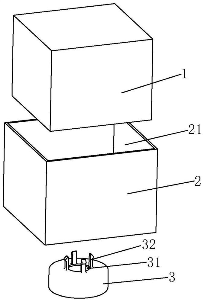
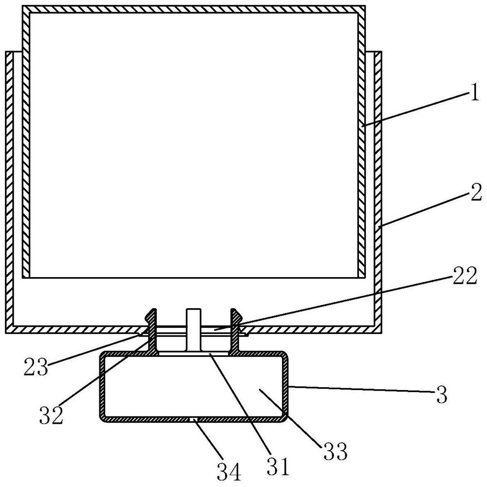
[0030] Examples, see Figure 2-Figure 8 As shown, a buoy device of the present invention is applied to a water tank, especially a toilet tank, and includes a buoy seat 2, a one-way switch 3 and a buoy 1 which is located in the buoy seat 2 and can be floated by buoyancy. 2 The upper end is provided with an opening 21 to prevent the water in the buoy 1 and the water supply tank from entering the buoy seat 2; the lower end of the buoy seat 2 is provided with a drain port 22, and the one-way switch 3 is movable at the drain port 22. And when this one-way switch 3 floats up to put in place, close this drain port 22; Drainage structure for drainage; after the buoy seat 2 is filled with water, the buoy 1 is subjected to the buoyancy effect (if the buoy is not subjected to the external force that limits its floating, the buoy can float), and a part of the water in the buoy seat 2 is released from the buoyancy. The water inlet structure enters the water storage chamber 33, fills the w...


PUM


Abstract

The invention discloses a buoy device, a method for controlling a buoy to fall in time, a water inlet valve and a drainage valve, the buoy device comprises a buoy seat, a one-way switch and a buoy located in the buoy seat, a drainage port is formed in the lower end of the buoy seat, the one-way switch is movably installed at the drainage port, and the drainage port is closed when the one-way switch floats in place; the one-way switch is provided with a water storage cavity, a water inlet structure communicated with the water storage cavity and an inner cavity of the buoy seat, and a drainage structure capable of draining water from the water storage cavity; after water enters the buoy seat, a part of water in the buoy seat enters the water storage cavity from the water inlet structure until the one-way switch opens the water outlet of the buoy seat. The buoy device enables the buoy to fall down in time along with the water level of a water tank, and ensures that a part linked with the buoy can act in time, so that the drain valve applying the buoy device can stop water in time, and the purpose of saving water is achieved.

Description

technical field [0001] The invention relates to the field of sanitary ware, in particular to a buoy device, a method for controlling the timely drop of the buoy, a water inlet valve, and a water discharge valve. Background technique [0002] In the toilet water parts, the lifting drive mechanism of the buoy is often used to move. For example, the buoy of the water inlet valve controls the opening and closing of the water inlet channel of the water inlet valve by lifting the buoy, and the buoy of the drain valve drives the valve plate to open by rising. In order to make the buoy move in place quickly, the buoy is usually placed in a buoy seat (or called an outer buoy). lift up. In order to ensure that the buoy can fall after the water level drops, a one-way switch is usually installed at the lower end of the buoy seat. When the water level rises, the one-way switch closes the drain outlet at the lower end of the buoy seat. Influx from the top of the buoy seat; after the wat...

Claims


Application Information

Patent Timeline
IPC IPC(8): E03D1/33E03D1/36E03D1/30
CPCE03D1/33E03D1/36E03D1/30E03D1/304
Inventor 林孝发林孝山黄冠乔
Owner JOMOO KITCHEN & BATHROOM
Why Eureka
Try Eureka