
Road and bridge safety detection device and detection method thereof

A safety inspection and bridge technology, applied in measurement devices, transportation and packaging, optical testing flaws/defects, etc., can solve the problems of vehicle and pedestrian safety hazards, safety accidents, poor versatility, etc., to achieve the effect of strong versatility

Inactive Publication Date: 2021-08-03
温州方舵建筑有限公司
View PDF0 Cites 1 Cited by
  • Summary
  • Abstract
  • Description
  • Claims
  • Application Information

AI Technical Summary

Problems solved by technology

[0002] At present, bridges generally refer to structures erected on rivers, lakes and seas to allow vehicles and pedestrians to pass smoothly. Bridges are generally composed of superstructures, substructures, supports and auxiliary structures. As time goes by, bridges will gradually age. Due to Due to various restrictions such as natural weather and its own materials, bridges will have cracks, which will pose a great safety hazard to passing vehicles and pedestrians, and safety accidents may occur. Therefore, it is particularly important to detect the safety of road bridges, so roads are required. Bridge Safety Detection Device
[0003] However, the current road and bridge safety detection device still has poor versatility, does not have a buffering effect, and cannot produce clear effects on roads and bridges, which is inconvenient for staff to watch the situation of roads and bridges, and the detection effect on roads and bridges is poor. Convenience question

Method used


Image

  • Road and bridge safety detection device and detection method thereof
  • Road and bridge safety detection device and detection method thereof
  • Road and bridge safety detection device and detection method thereof

Examples


Embodiment Construction

[0037] Embodiments of the present invention are described below through specific examples, and those skilled in the art can easily understand other advantages and effects of the present invention from the content disclosed in this specification. The present invention can also be implemented or applied through other different specific implementation modes, and various modifications or changes can be made to the details in this specification based on different viewpoints and applications without departing from the spirit of the present invention. It should be noted that the diagrams provided in the following embodiments are only schematically illustrating the basic concept of the present invention, and the following embodiments and the features in the embodiments can be combined with each other in the case of no conflict.

[0038] Wherein, the accompanying drawings are for illustrative purposes only, and represent only schematic diagrams, rather than physical drawings, and should...


PUM


Abstract

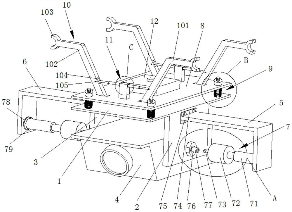
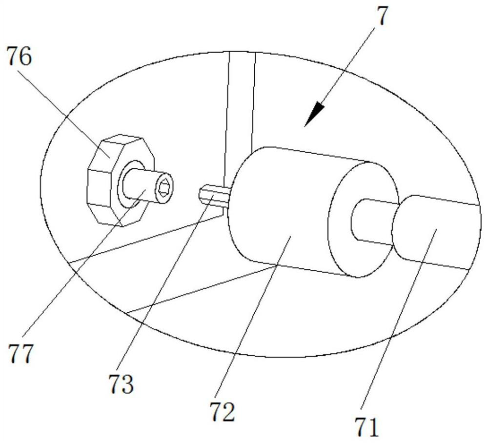
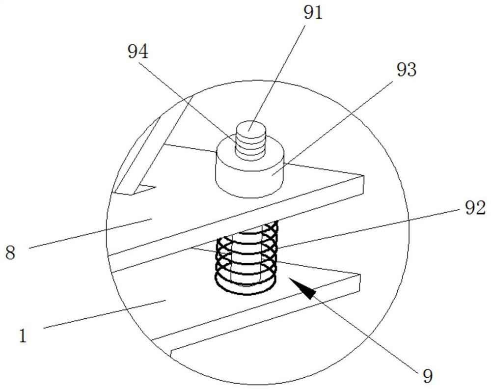
The invention discloses a road and bridge safety detection device and a detection method thereof. The road and bridge safety detection device comprises a lower supporting plate; a first side protection plate and a second side protection plate are fixed to the two side walls of the lower supporting plate correspondingly; a camera is hinged between the first side protection plate and the second side protection plate; the first side protection plate is connected with an inclination angle adjusting mechanism; the second side protection plate is connected with a second L-shaped bracket; the second L-shaped bracket is connected with an inclination angle adjusting mechanism; the camera is hinged between the two inclination angle adjusting mechanisms; the lower supporting plate is connected with an upper supporting plate through a buffer mechanism; two clamping power mechanisms are arranged on the upper supporting plate; remote control aircraft clamping mechanisms are hinged to the two ends of each clamping power mechanism respectively. The road and bridge safety detection device is high in universality, has a buffering effect, can shoot a road and bridge clearly, is convenient for workers to watch conditions of the road and bridge, has a good detection effect on the road and bridge, and is convenient to use.

Description

technical field [0001] The invention belongs to the technical field of roads and bridges, in particular to a road and bridge safety detection device and a detection method thereof. Background technique [0002] At present, bridges generally refer to structures erected on rivers, lakes and seas to allow vehicles and pedestrians to pass smoothly. Bridges are generally composed of superstructures, substructures, supports and auxiliary structures. As time goes by, bridges will gradually age. Due to Due to various restrictions such as natural weather and its own materials, bridges will have cracks, which will pose a great safety hazard to passing vehicles and pedestrians, and safety accidents may occur. Therefore, it is particularly important to detect the safety of road bridges, so roads are required. Bridge safety detection device. [0003] However, the current road and bridge safety detection device still has poor versatility, does not have a buffering effect, and cannot prod...

Claims


Application Information

Patent Timeline
IPC IPC(8): G01N21/88G01N21/01F16M11/10F16M11/18F16M13/02F16F15/067B64D47/08
CPCG01N21/88G01N21/01F16M11/10F16M11/18F16M13/02F16F15/067B64D47/08G01N2201/0214H04N23/50
Inventor 程靖童
Owner 温州方舵建筑有限公司
Learn More