
Unmanned aerial vehicle track and intelligent reflecting surface phase shift joint optimization method and system

A technology of joint optimization and reflective surface, applied in the directions of radio transmission system, transmission system, wireless communication, etc., can solve problems such as difficult to solve, and achieve the effect of reducing power consumption, improving learning efficiency and large amount of calculation

Active Publication Date: 2021-07-30
XI AN JIAOTONG UNIV
View PDF7 Cites 13 Cited by
  • Summary
  • Abstract
  • Description
  • Claims
  • Application Information

AI Technical Summary

Problems solved by technology

[0006] The technical problem to be solved by the present invention is to provide a joint optimization method and system for the phase shift of the trajectory of the UAV and the phase shift of the intelligent reflector in view of the deficiencies in the above-mentioned prior art. Problems that are difficult for optimization methods to solve under the condition of constantly changing communication environment

Method used


Image

  • Unmanned aerial vehicle track and intelligent reflecting surface phase shift joint optimization method and system
  • Unmanned aerial vehicle track and intelligent reflecting surface phase shift joint optimization method and system
  • Unmanned aerial vehicle track and intelligent reflecting surface phase shift joint optimization method and system

Examples


Embodiment Construction

[0083] The invention provides a joint optimization method for UAV trajectory and intelligent reflective surface phase shift. Firstly, a wireless communication system model based on UAV and intelligent reflective surface is established. Secondly, aiming at the non-convexity of the trajectory and phase shift optimization problem, A method based on the deep deterministic policy gradient algorithm is proposed to realize the joint optimization of the UAV trajectory and the joint phase shift of the intelligent reflector.

[0084] The present invention relates to a joint optimization method for UAV trajectory and intelligent reflective surface phase shift, comprising the following steps:

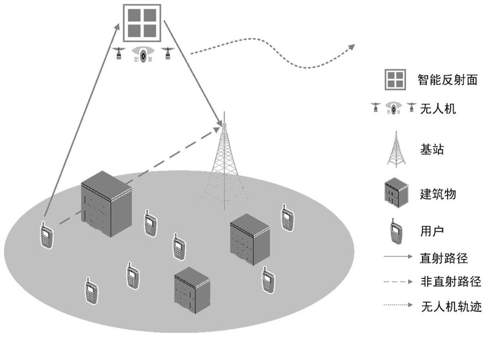
[0085] S1. Establish a wireless communication system model based on drones and smart reflectors, and then discuss the channels affected by the Doppler effect and the energy consumed by drones and smart reflectors;

[0086] communication model such as figure 1 As shown, it includes N ground users, ...


PUM


Abstract

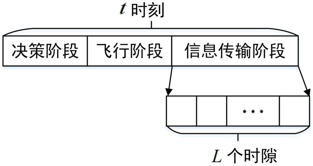
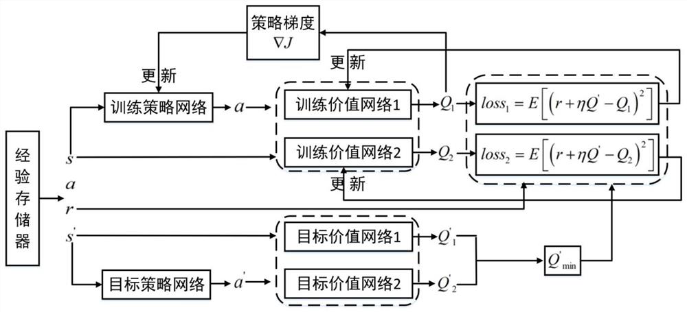
The invention discloses an unmanned aerial vehicle track and intelligent reflecting surface phase shift joint optimization method and system. A wireless communication system model assisted by an unmanned aerial vehicle and an intelligent reflecting surface is established, and the energy efficiency of the system is calculated; the position of the unmanned aerial vehicle is determined by using a priority experience playback TD3 method, the unmanned aerial vehicle and the intelligent reflecting surface assist a user communicating with the base station, an activated reflecting element of the intelligent reflecting surface in a first time slot in an information transmission stage and a phase shift of the activated reflecting element, then by using the priority experience playback TD3 method based on the LSTM, the activated reflecting elements of the intelligent reflecting surface in all time slots of the whole information transmission stage and phase shifts of the activated reflecting elements are obtained, the track of the unmanned aerial vehicle and the phase shift of the intelligent reflecting surface are adaptively adjusted according to the communication environment, and joint optimization of the track of the unmanned aerial vehicle and the phase shift of the intelligent reflecting surface is completed. The problem that an off-line optimization method for the track of the unmanned aerial vehicle and the displacement of the intelligent reflecting surface is difficult to solve under the condition that the communication environment changes continuously is solved.

Description

technical field [0001] The invention belongs to the technical field of wireless communication, and in particular relates to a joint optimization method and system for the trajectory of an unmanned aerial vehicle and the phase shift of an intelligent reflective surface. Background technique [0002] UAVs can be flexibly deployed in high and low altitudes as mobile communication stations, without the limitations of unfavorable factors such as distance and terrain, and can easily establish line-of-sight transmission links with base stations, ground users, and other equipment in the communication network to further expand Network coverage, improve communication quality. Although the use of drones will bring many benefits, since drones can only rely on their own batteries to provide energy during flight, power consumption will become a bottleneck that limits the performance of drones. [0003] On the other hand, with the advent of the 5G era, the performance of wireless communic...

Claims


Application Information

Patent Timeline
Patent Type & Authority Applications(China)
IPC IPC(8): H04W24/02H04W24/08H04B7/185H04B17/391
CPCH04W24/02H04W24/08H04B7/18504H04B17/391Y02D30/70
Inventor 张超亓乾月
Owner XI AN JIAOTONG UNIV
Learn More