
Field geophysical prospecting test landfill space positioning device and method

A space positioning and landfill technology, which is applied in the field of field tests, can solve the problems of inaccurate spatial positioning of landfills, achieve low cost, light equipment, and improve measurement efficiency

Active Publication Date: 2021-07-30
SHANDONG UNIV
View PDF5 Cites 1 Cited by
  • Summary
  • Abstract
  • Description
  • Claims
  • Application Information

AI Technical Summary

Problems solved by technology

[0005] In order to overcome the problem that the existing technology cannot accurately locate landfills in field geophysical exploration tests, the present invention provides a space positioning device and method for landfills in field geophysical exploration tests

Method used


Image

  • Field geophysical prospecting test landfill space positioning device and method
  • Field geophysical prospecting test landfill space positioning device and method
  • Field geophysical prospecting test landfill space positioning device and method

Examples


Embodiment 1

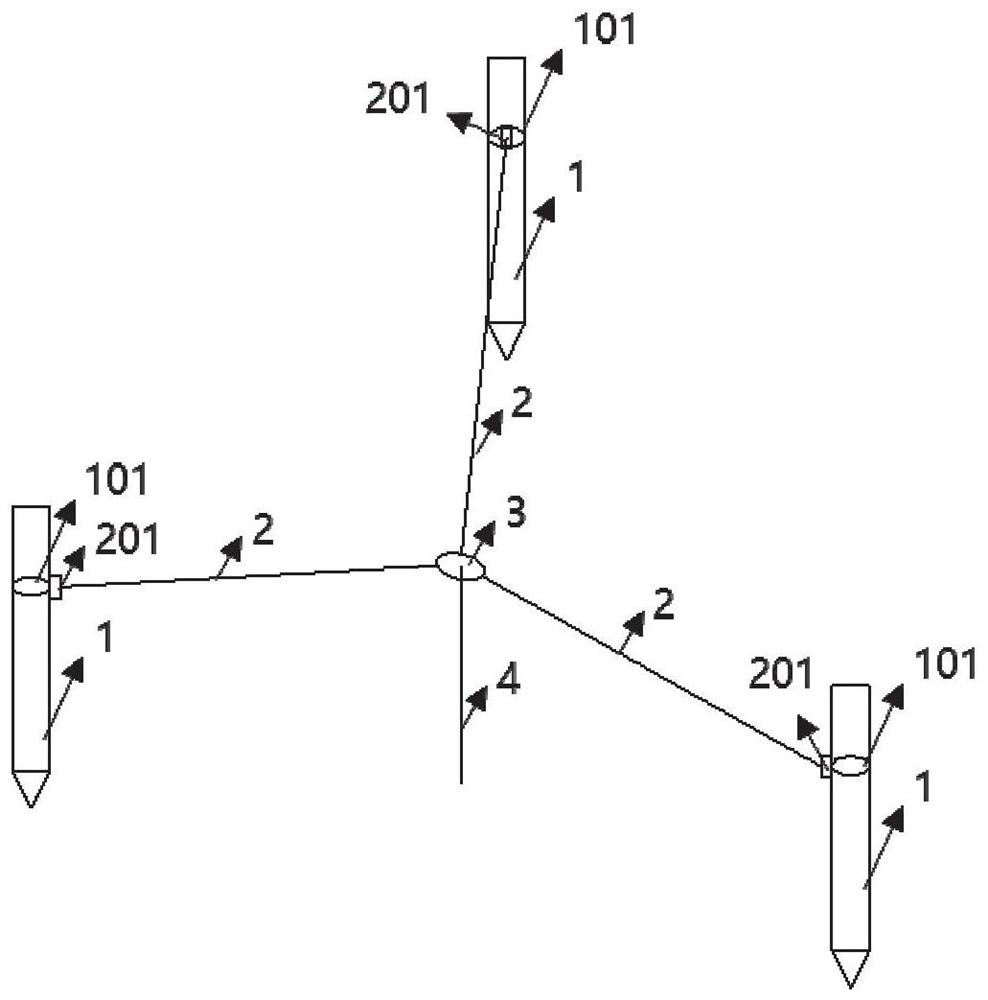
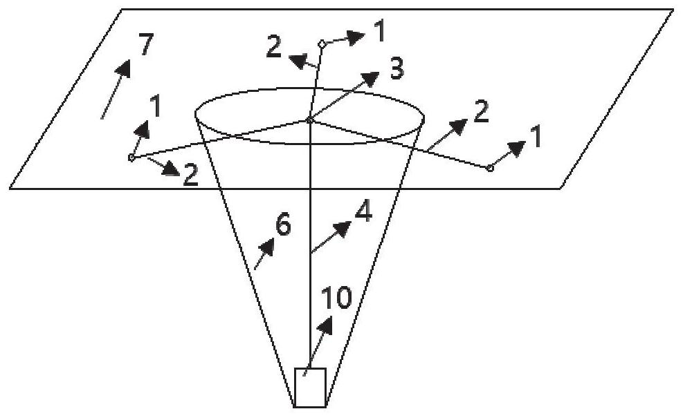
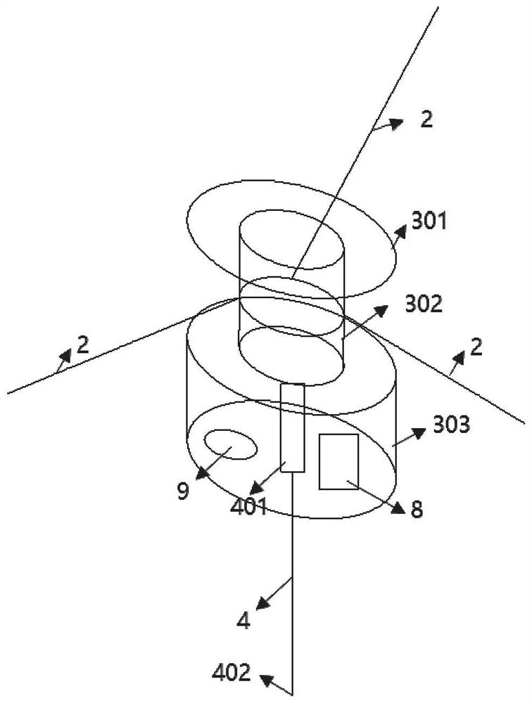
[0038] A special implementation of the present application is applied to the construction of landfill positioning in field geophysical prospecting model tests. Such as figure 1As shown, a field geophysical exploration test landfill space positioning device disclosed in this embodiment includes an anchor rod 1, a first ruler 2, a junction box 3, a second ruler 4, and a remote control switch 5; There are three anchor rods 1, which can be fixed on the ground 7 outside the pothole 6 to form a triangular area, which lays the foundation for the subsequent spatial positioning calculation. Preferably, after the three anchor rods 1 are fixed, an equilateral triangular area is formed . There are also three first rulers 2, one end is the fixed end 201 bound to the anchor rod 1, and the other end is the movable end 202 fixed on the junction box 3; One ruler 2 is connected with three anchor rods 1, one first ruler corresponds to one anchor rod 1; the second ruler 4 is provided with one, ...

Embodiment 2

[0059] A special implementation of the present application is applied to the construction of landfill positioning in field geophysical prospecting model tests. The concept of this embodiment is basically the same as that of Embodiment 1. The landfill space positioning device for field geophysical exploration tests also includes a first chi 2, a junction box 3, a second chi 4, and a remote control switch 5; The difference is that the anchor rod 1 is omitted, and the fixed end 201 of the first ruler 2 is bound to the outer support of the pit 6; other structures are exactly the same as those in Embodiment 1, and will not be repeated here.

[0060] Of course, it is not difficult to understand that the supports described in this embodiment can be fixed facilities such as tree trunks and buildings; the first ruler fixed end 201 is bound to the supports and is detachable.

[0061] In the corresponding part of the method, this embodiment also provides a method for spatial positioning ...


PUM


Abstract

The invention discloses a field geophysical prospecting test landfill space positioning device which comprises three anchoring rods, three first rulers, a junction box, a second ruler and a remote control switch. The three anchoring rods can be fixed on the ground on the outer side of the pit edge; the fixed ends of the first rulers are bound with the anchoring rod, and the movable ends of the first rulers are fixed on the junction box; one end of the second ruler is a fixed end bound with the junction box, and the other end of the second ruler is a movable end; the first ruler fixed ends and the second ruler fixed end are respectively provided with a control circuit which controls the first ruler fixed end and the second ruler fixed end to fold and unfold respective movable ends. The remote control switch wirelessly and remotely controls each control circuit to work. According to the field geophysical prospecting test landfill space positioning method, three second rulers are adopted, and the three-side positioning principle is combined to measure the position of a landfill at the bottom of a suspended pit.

Description

technical field [0001] The invention relates to field test directions in geophysical prospecting, in particular to a space positioning device and method for landfills in field geophysical prospecting tests. Background technique [0002] Geophysical exploration, referred to as geophysical prospecting, refers to the detection of geological conditions such as stratum lithology and geological structure by studying and observing changes in various geophysical fields. This method has the advantages of portable equipment, low cost, high efficiency, and wide working space, and is widely used in archaeology, tunnel construction, urban pipeline detection, hydrogeological survey and other fields. [0003] Field geophysical prospecting test refers to carrying out corresponding geophysical prospecting tests by pre-burying unfavorable geological bodies in the actual stratum in the field, so as to obtain comprehensive and real responses of various geophysical prospecting methods under diff...

Claims


Application Information

Patent Timeline
Patent Type & Authority Applications(China)
IPC IPC(8): G01V9/00
CPCG01V9/00
Inventor 薛翊国张开王鹏苏茂鑫曲传奇程凯韩敏潘登
Owner SHANDONG UNIV
Learn More