Eureka AIR delivers breakthrough ideas for toughest innovation challenges, trusted by R&D personnel around the world.

Automatic width and thickness measuring clamp for wires

An automatic and width-measuring technology, which is applied in the direction of measuring devices, manufacturing tools, workpiece clamping devices, etc., can solve problems such as the inability to fix multiple wires of different shapes and volumes, the inability to adjust the distance between fixtures, and the large difference in wire shapes. , to save measurement time, easy to fix, and improve efficiency

Pending Publication Date: 2021-07-30
TAIZHOU VOCATIONAL & TECHN COLLEGE
View PDF6 Cites 2 Cited by
  • Summary
  • Abstract
  • Description
  • Claims
  • Application Information

AI Technical Summary

Problems solved by technology

[0003] When measuring the width and thickness of the wire, it is necessary to fix the wire so that the wire remains stable and avoids measurement errors caused by wire folding. Different wire shapes vary greatly. The previous wire clamps cannot fix multiple wires of different shapes and volumes, and cannot adjust the wire according to the size of the wire. Adjust the distance between the clamps for the length of the

Method used


Image

  • Automatic width and thickness measuring clamp for wires
  • Automatic width and thickness measuring clamp for wires
  • Automatic width and thickness measuring clamp for wires

Examples


Embodiment Construction

[0024] The following will clearly and completely describe the technical solutions in the embodiments of the present invention with reference to the accompanying drawings in the embodiments of the present invention. Obviously, the described embodiments are only some, not all, embodiments of the present invention. Based on the embodiments of the present invention, all other embodiments obtained by persons of ordinary skill in the art without making creative efforts belong to the protection scope of the present invention.

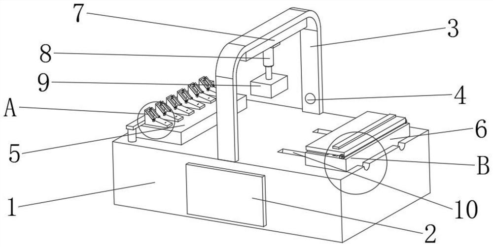
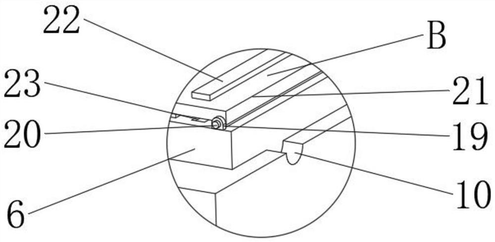
[0025] see Figure 1-7 , in an embodiment of the present invention, a fixture for automatic width and thickness measurement of wires includes a workbench 1, a fixed mount 5 is fixedly connected to the upper surface of one end of the workbench 1, and a plurality of fixed mounts are fixedly installed on the upper surface of the fixed mount 5. Block 12, the upper end of the fixed block 12 is provided with a through hole 16, the first mounting part 15 is fixedly i...


PUM


Abstract

The invention discloses an automatic width and thickness measuring clamp for wires in the technical field of wire fixing devices, which comprises a worktable. A fixed mounting seat is fixedly connected to the upper surface of one end of the worktable, a plurality of fixed blocks are fixedly mounted on the upper surface of the fixed mounting seat, and through holes are formed in the upper ends of the fixed blocks. First mounting pieces are fixedly mounted on the two sides of the fixed block and correspond to the lower portions of the through holes, first connecting shafts are fixedly connected to the upper ends of the first mounting pieces, movable pressing rings are rotationally connected to the first connecting shafts, clamping blocks are fixedly connected to the upper ends of the sides, away from the through holes, of the movable pressing rings, and clamping grooves are formed in the upper surface of the fixing block; a movable groove is formed in the end, away from the fixed mounting base, of the upper surface of the workbench, a movable mounting base is slidably connected to the movable groove, and a plurality of balls are rotationally connected to the lower portion of the movable mounting base. By means of the device, the wire can be fixed more conveniently and rapidly, the wire can be straightened conveniently, and errors of the measurement result caused by bending of the measurement position are avoided.

Description

technical field [0001] The invention relates to the technical field of wire fixing devices, in particular to a jig for automatic wire width and thickness measurement. Background technique [0002] Wire rod is the smallest section size of hot-rolled section steel. In my country, the hot-rolled round steel supplied in coils with a diameter of 5-9 mm and a total of eight specifications is called wire rod. Wire rod is also called wire rod because it is delivered in coils. The concept of wire rod in foreign countries is slightly different from that in my country. There are other shapes besides circular cross-section, and its diameter is inconsistent due to different demand conditions and production technology levels. [0003] When measuring the width and thickness of the wire, it is necessary to fix the wire so that the wire remains stable and avoids measurement errors caused by wire folding. Different wire shapes vary greatly. The previous wire clamps cannot fix multiple wires...

Claims


Application Information

Patent Timeline
Patent Type & Authority Applications(China)
IPC IPC(8): G01B21/02G01B21/08B25B11/00
CPCG01B21/02G01B21/08B25B11/002
Inventor 金珍珍
Owner TAIZHOU VOCATIONAL & TECHN COLLEGE
Why Eureka
Eureka Blog
Learn More