Safety belt falling protector

A technology of safety belt and anti-fall device, applied in the field of anti-drop device, can solve the problems of inconvenient fixing and poor safety of the anti-drop device, and achieve the effects of easy promotion and application, good fixing effect and good practicability.

Active Publication Date: 2022-03-01
泰州协力吊装设备有限公司
View PDF9 Cites 0 Cited by
  • Summary
  • Abstract
  • Description
  • Claims
  • Application Information

AI Technical Summary

Problems solved by technology

[0004] The object of the present invention is to provide a safety belt fall arrester to solve the problems of inconvenient fixing and poor safety of the existing fall arrester proposed in the above-mentioned background technology

Method used


Image

  • Safety belt falling protector
  • Safety belt falling protector
  • Safety belt falling protector

Examples


Embodiment 1

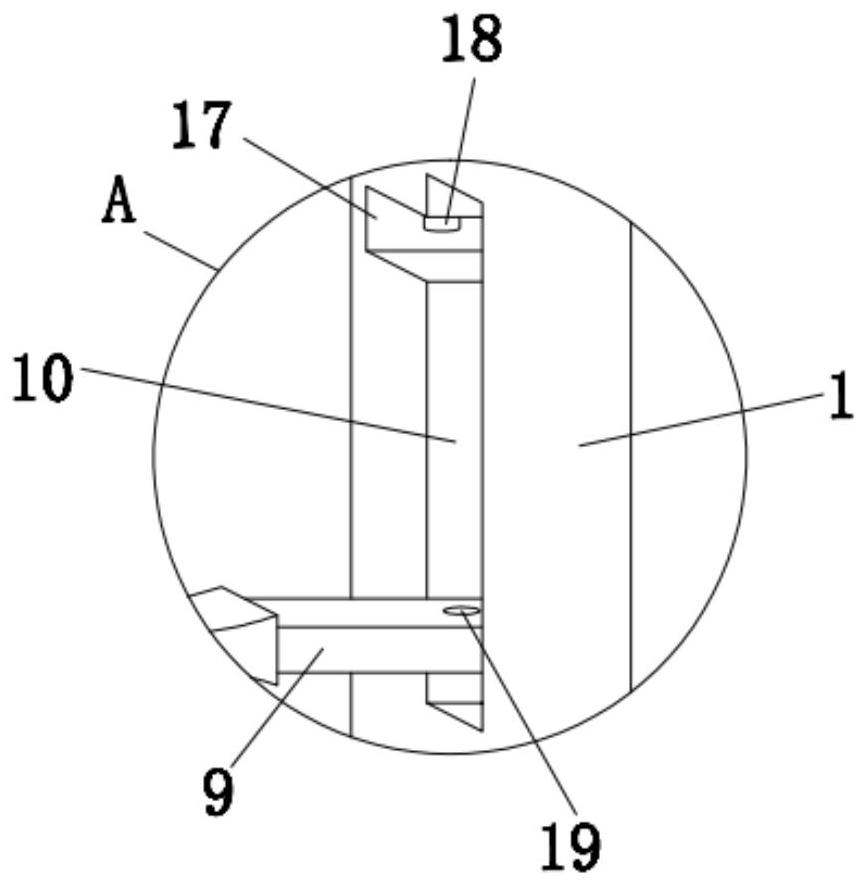
[0025] Embodiment 1, see Figure 1-Figure 3 , the present invention provides a technical solution: a safety belt fall arrester, including a box body 1, the bottom end of the box body 1 is equipped with a safety belt 5, the safety belt 5 is the prior art, can be selected according to the needs of use, and can be combined with This device is connected together, and the bottom left side of box body 1 is provided with handle 7, and handle 7 is used for the staff to grasp, and the inner cavity of box body 1 is equipped with the gear 12 that can rotate around its own axis direction through the rotating shaft, and the gear 12 The left and right sides are connected with a rack one 11 and a rack two 15 respectively along the up and down direction. In order to strengthen the stability of the rack one 11, the rack one 11 can be embedded in the bar-shaped groove provided on the inner wall of the box body 1. The first rack 11 and the second rack 15 are staggered relative to the gear 12. Wh...

Embodiment 2

[0030] Example 2, see Figure 4-7 , the present invention provides another technical solution: a safety belt fall arrester, including a box body 1, the bottom end of the box body 1 is equipped with a safety belt 5, the safety belt 5 is the prior art, can be selected according to the needs of use, and Connected with this device, the left bottom of the box body 1 is provided with a handle 7, the handle 7 is used for the staff to grasp, the inner cavity of the box body 1 is equipped with a gear 12 that can rotate around its own axis through a rotating shaft, and the gear 12 Rack one 11 and rack two 15 are connected to the left and right sides of the rack respectively along the up and down direction. In order to strengthen the stability of rack one 11, the rack one 11 can be embedded in the bar-shaped groove provided on the inner wall of the box body 1. Rack 1 11 and rack 2 15 are interlaced relative to gear 12. When gear 12 rotates, rack 1 11 and rack 2 15 can be moved in opposit...


PUM


Abstract

The invention relates to the technical field of falling protectors, and discloses a safety belt falling protector which comprises a box body, a gear capable of rotating around the axis direction of the gear is assembled in an inner cavity of the box body through a rotating shaft, and the left side and the right side of the gear are in engaged connection with a first rack and a second rack in the vertical direction correspondingly. One end of a first spring is arranged at the bottom end of the first rack, a driving mechanism is assembled at the top end of the left side of the first rack, a rotating mechanism is assembled at the top end of the second rack, one end of a hanging rod is assembled at the top end of the rotating mechanism, and the other end of the hanging rod penetrates through the box body. And a plurality of matched limiting cylinders are assembled at the top end of the box body by taking the suspension rod as the center. The fixing device can be conveniently fixed to a frame of a steel structure when workers work aloft, fixing is convenient and easy, the fixing effect is good, and the personal safety of constructors is guaranteed.

Description

technical field [0001] The invention relates to the technical field of fall arresters, in particular to a safety belt fall arrester. Background technique [0002] In the power system, transformers, lightning arresters, isolating switches, etc. are important primary electrical equipment in substations. There are a large number of them. These electrical equipment are installed on the support frame. Various structural parts are combined by welding or bolting. In order to save space and make reasonable use of space, the height of the steel structure is often made very high. Avoid working at heights. These structural parts are generally made of section steel, usually channel steel, I-beam, steel pipe, round steel, steel plate, etc. Channels are commonly used on major structural members such as gauges and columns. During the high-altitude construction work on such steel structures, there is often no reliable solid foundation member to hang the safety belt near the construction ...

Claims


Application Information

Patent Timeline
IPC IPC(8): A62B35/00
CPCA62B35/0043A62B35/0068
Inventor 徐小兵徐泽宇贾美红
Owner 泰州协力吊装设备有限公司
Why Eureka
Try Eureka