
Hypoid adjustable gap gear speed reducer and adjusting and testing method

A technology of gear reduction and hypoid, which is applied in the field of gear reducers. It can solve problems such as the limitation of installation angle, the inability to directly install the drive shaft, and the inability to select the output speed according to the needs, so as to improve the installation range and ensure the sealing effect. Ease of use

Active Publication Date: 2021-07-30
杭州誉球机械有限公司
View PDF5 Cites 1 Cited by
  • Summary
  • Abstract
  • Description
  • Claims
  • Application Information

AI Technical Summary

Problems solved by technology

[0004] Aiming at the deficiencies of the prior art, the present invention provides a hypoid adjustable gap gear reducer and its adjustment and testing method, which solves the problem that some existing simple gear reducers have a fixed transmission ratio and cannot select different output speeds according to needs. , and the installation direction of the input and output shafts of the existing gear reducer is fixed, and the two drive shafts that are not 90 degrees cannot be directly installed, and the installation angle has limitations.

Method used


Image

  • Hypoid adjustable gap gear speed reducer and adjusting and testing method
  • Hypoid adjustable gap gear speed reducer and adjusting and testing method
  • Hypoid adjustable gap gear speed reducer and adjusting and testing method

Examples


Embodiment 1

[0046] Embodiment 1, when the housing 1 is laid flat and fixed:

[0047] see Figure 6-8 , the outside of the housing 1 is provided with a bracket 5, the bracket 5 includes a base 51, the four corners of the base 51 are provided with bolt mounting holes, the top of the base 51 is fixedly connected with four positioning blocks 52, and the center of the top of the base 51 is bonded with a buffer Pad 53, the lower fixing seat 14 is fixedly connected between the front and rear sides and the bottom of the shell 1, and the upper fixing seat 15 is fixedly connected to the left and right sides of the rear top of the casing 1, and the two upper fixing seats 15 are respectively located on the two sides of the rear side. On one side of the two positioning blocks 52 facing away from each other, two lower fixing seats 14 are sleeved on the outside of the two positioning blocks 52 on the front side, and the first screw rod 6 is passed between the positioning block 52 and the lower fixing se...

Embodiment 2

[0048] Embodiment 2, when the housing 1 is erected and fixed:

[0049] see Figure 6 and 9 , the outside of the housing 1 is provided with a bracket 5, the bracket 5 includes a base 51, the four corners of the base 51 are provided with bolt mounting holes, the top of the base 51 is fixedly connected with four positioning blocks 52, and the center of the top of the base 51 is bonded with a buffer Pad 53, the lower fixing seat 14 is fixedly connected between the front and rear sides and the bottom of the shell 1, and the upper fixing seat 15 is fixedly connected to the left and right sides of the rear top of the casing 1, and the two lower fixing seats 14 are erected on the left and right groups. The side facing away from the positioning block 52 and the front and rear sides of the bottom of the lower fixing base 14 are fixedly connected through the second screw rod 7 to the positioning block 52 .

[0050] By providing a corresponding connection structure on the bracket 5 and ...


PUM


Abstract

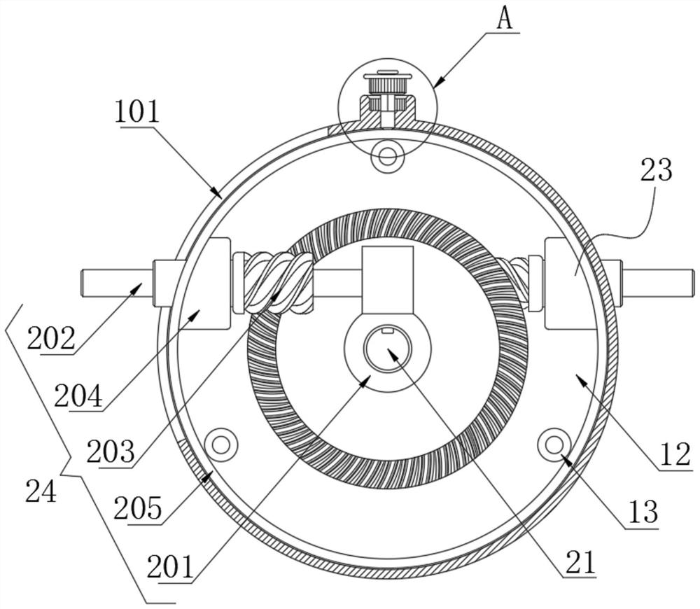
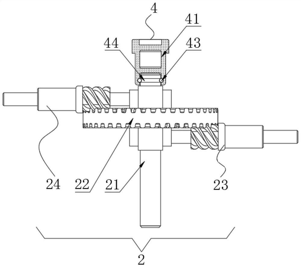
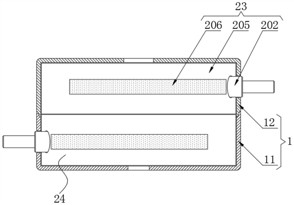
The invention discloses a hypoid adjustable gap gear speed reducer and an adjusting and testing method, and relates to the technical field of gear speed reducers. The hypoid adjustable gap gear speed reducer comprises a shell and a transmission assembly arranged in the shell; the transmission assembly comprises an input shaft which penetrates through the front portion and the rear portion and is rotationally connected to the center of the shell; and a double-face gear is fixedly connected to the middle of the input shaft. According to the hypoid adjustable gap gear speed reducer and the adjusting and testing method, transmission mechanisms are arranged on the two sides of the double-face gear, different transmission ratios can be achieved between output shafts of the two transmission mechanisms and the double-face gear, and therefore different speed reduction requirements can be met; the two transmission mechanisms can rotate by a certain angle to conduct output, connection with shafts of different angles is facilitated, and the installation range is greatly enlarged; a rotary barrel is arranged outside the hypoid adjustable gap gear speed reducer, and the sealing effect can be guaranteed when the angle is rotationally adjusted; and a rotary barrel fixing mechanism is arranged to be matched with the rotary barrel, the angles of the transmission mechanisms can be fixed, stable output is guaranteed, and use is convenient.

Description

technical field [0001] The invention relates to the technical field of gear reducers, in particular to a hypoid adjustable clearance gear reducer and an adjustment and testing method. Background technique [0002] The reducer is an independent component composed of gear transmission, worm transmission, and gear-worm transmission enclosed in a rigid shell. It is often used as a reduction transmission device between the prime mover and the working machine. It plays the role of matching speed and transmitting torque between prime mover and working machine or actuator, and is widely used in modern machinery. The reducer is generally used for low-speed and high-torque transmission equipment. The motor, internal combustion engine or other high-speed running power is used to achieve the purpose of deceleration through the gear with a small number of teeth on the input shaft of the reducer and the large gear on the output shaft. Ordinary The reducer will also have several pairs of ...

Claims


Application Information

Patent Timeline
Patent Type & Authority Applications(China)
IPC IPC(8): F16H57/021F16H57/023F16H57/025F16H57/12F16H3/02G01M13/025G01M13/028
CPCF16H57/021F16H57/023F16H57/025F16H57/12F16H3/02F16H3/001G01M13/025G01M13/028
Inventor 徐国
Owner 杭州誉球机械有限公司
Learn More