
Electromagnetic chuck type friction limited slip differential

A limited-slip differential and differential technology, applied in the direction of differential transmission, belt/chain/gear, mechanical equipment, etc., can solve the problems of easy slippage, loss of traction, insufficient wheel adhesion, etc.

Pending Publication Date: 2021-07-30
WENLING HUAXIN MACHINERY MFG
View PDF1 Cites 0 Cited by
  • Summary
  • Abstract
  • Description
  • Claims
  • Application Information

AI Technical Summary

Problems solved by technology

The disadvantage of the ordinary planetary gear differential is that when the vehicle is driving on a muddy and slippery road, due to insufficient adhesion of the wheels, it is easy to slip and lose traction

Method used


Image

  • Electromagnetic chuck type friction limited slip differential
  • Electromagnetic chuck type friction limited slip differential
  • Electromagnetic chuck type friction limited slip differential

Examples


Embodiment 1

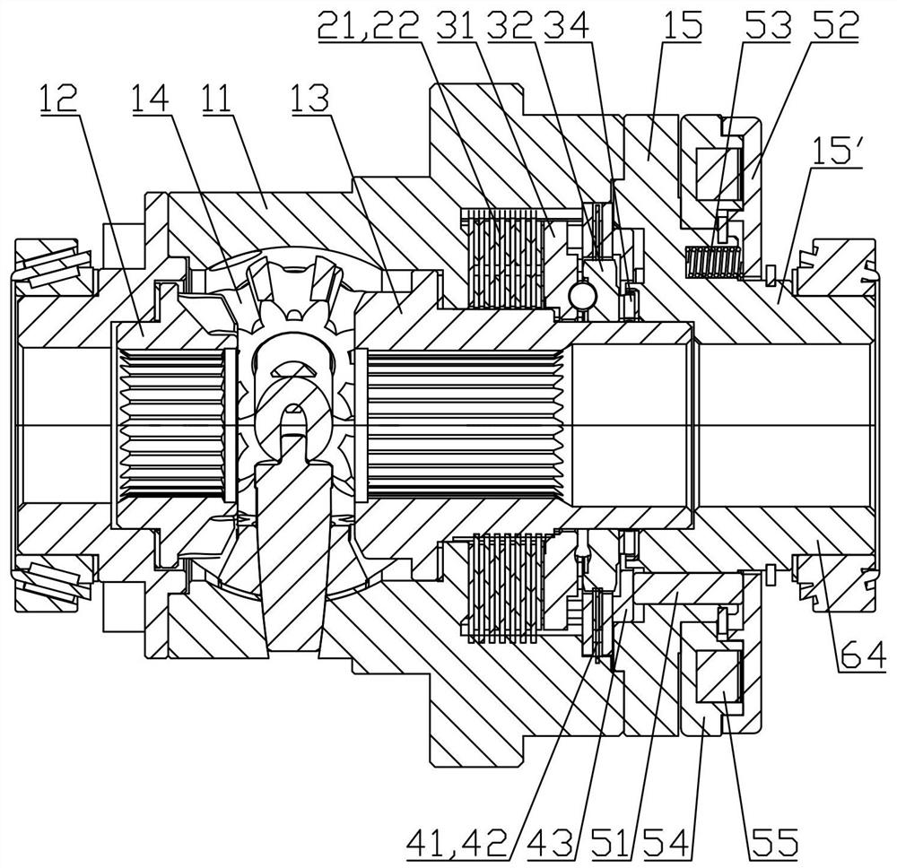
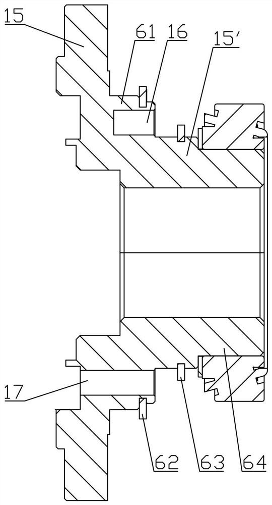
[0027] refer to figure 1, an electromagnetic chuck type friction limited-slip differential provided in this embodiment includes a differential housing 11, a left side gear 12, a right side gear 13, and simultaneously with the left and right side gears 12 and 13 respectively. The meshed planetary gear 14 also includes a limited-slip friction pair, a limited-slip actuator, a leading friction pair and a The right front actuation assembly. Wherein, the limited-slip friction pair has a plurality of first friction plates 21 connected to the differential case 11 and a plurality of second friction plates 22 connected to the right side gear 13, and the limited-slip actuator includes the first The relative rotation actuator of a cam plate 31 and the second cam plate 32, the leading friction pair has a plurality of third friction plates 41 connected to the differential case 11 and a plurality of third friction plates 41 connected to the second cam plate 32. The fourth friction plate 42...

Embodiment 2

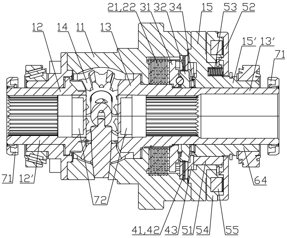
[0037] The structure of this embodiment is basically the same as that of Embodiment 1, the difference is: refer to image 3 , the left side shaft gear 12 and the right side shaft gear 13 are used to connect the shaft sleeve parts 12' and 13' of the left and right shaft shafts, and both extend axially outward and extend out of the differential case 11. The shaft sleeve part 12' , 13' protruding from the differential housing 11 through the oil seal 71 and the shaft holes at the two ends of the axle reduction box (not shown in the figure) are sealed and connected, and the shafts of the left and right side gears 12 and 13 Plugs 72 are sealingly connected to the inner ends, and a sealed cavity is formed between the plugs 72, the side gears 12, 13, the oil seal 71 and the reduction box. This structure forms a self-sealing when the left and right half shafts are not installed, so lubricating oil can be added without the half shafts being installed and the interior will not be pollute...


PUM


Abstract

The invention discloses an electromagnetic chuck type friction limited slip differential and belongs to the technical field of differentials. According to the electromagnetic chuck type friction limited slip differential, a slip limiting friction pair, a slip limiting actuator and a pilot friction pair are sequentially arranged between a right half axle gear and a differential shell, the electromagnetic chuck type friction limited slip differential further comprises a pilot actuating assembly, the pilot actuating assembly comprises a plurality of push rods, an electromagnetic clutch and a chuck, the electromagnetic clutch and the chuck are arranged outside the differential shell, the push rods are inserted in a right end cover of the differential shell, and reset springs are arranged between the chuck and the right end cover. When the electromagnetic clutch is powered on, the chuck can be attracted to move leftwards to push the push rods to tightly press the pilot friction pair, so that two cam discs of the slip limiting actuator rotate relatively to actuate and press the slip limiting friction pair, and therefore the right half axle gear is connected with the differential shell to achieve locking and slip limiting. The electromagnetic chuck type friction limited slip differential is compact in structure, small in size, large in thrust, high in response speed, good in slip limiting effect, easy to manufacture and low in cost.

Description

technical field [0001] The invention relates to the technical field of differentials, in particular to an electromagnetic sucker type friction limited-slip differential. Background technique [0002] The differential is an important part of the vehicle's power transmission system. Its function is to realize the differential speed when the wheel speeds on both sides of the drive shaft are inconsistent (such as when the vehicle is turning), so as to avoid wheel slippage and reduce driving resistance and tire wear. The disadvantage of the ordinary planetary gear differential is that when the vehicle is driving on a muddy and slippery road, due to insufficient adhesion of the wheels, it is easy to slip and lose traction. [0003] In order to solve the problem of vehicle slippage, people have developed a friction plate type limited-slip differential. For example, a Chinese patent disclosed an electronically controlled multi-plate self-locking drive axle on March 9, 2016. The publ...

Claims


Application Information

Patent Timeline
IPC IPC(8): F16H48/22F16H48/34
CPCF16H48/22F16H48/34
Inventor 张宇荣
Owner WENLING HUAXIN MACHINERY MFG
Learn More