
Rescue device for water conservancy project

A technology for water conservancy projects and rescue clothing, which is applied in hoisting devices, water lifesaving, transportation and packaging, etc. It can solve problems such as hidden dangers, unbalanced fixing force, and difficulties for rescuers, so as to improve rescue efficiency, speed and flexibility. The effect of deployment

Active Publication Date: 2021-07-30
韩伟
View PDF5 Cites 0 Cited by
  • Summary
  • Abstract
  • Description
  • Claims
  • Application Information

AI Technical Summary

Problems solved by technology

[0002] Water conservancy projects are projects built to control and allocate natural surface water and groundwater to achieve the purpose of eliminating harm and promoting benefits. When tourists or pedestrians walk and play beside the river, unexpected accidents may cause tourists or pedestrians to fall. When entering the water, there may be certain hidden dangers due to the flow rate of the water, which will bring great difficulties to the rescuers. Therefore, the existing rescue devices will be bound to the rescuers through ropes, so that the rescuers have safety guarantees when they rescue. Some rescue devices are divided into portable mobile and fixed. The fixed method of the portable and mobile type is only provided by the gravity of the personnel on the shore. The danger of rescue work is increased, and the fixed type is to deploy a certain number of rescue devices on the river bank in advance, and its stability exists, but once a distress situation occurs, these devices will be far away from these fixed rescue devices. will not work well

Method used


Image

  • Rescue device for water conservancy project
  • Rescue device for water conservancy project
  • Rescue device for water conservancy project

Examples


specific Embodiment approach

[0049] Based on the above scheme, the specific implementation of the rescue device for water conservancy projects is as follows:

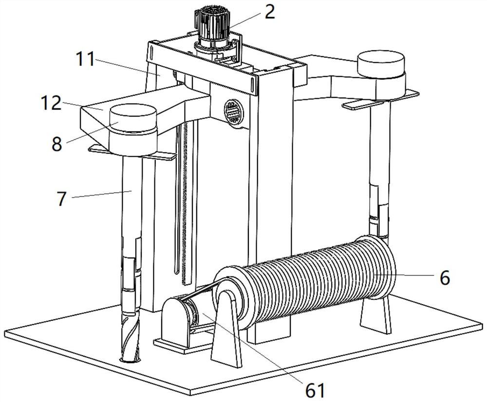
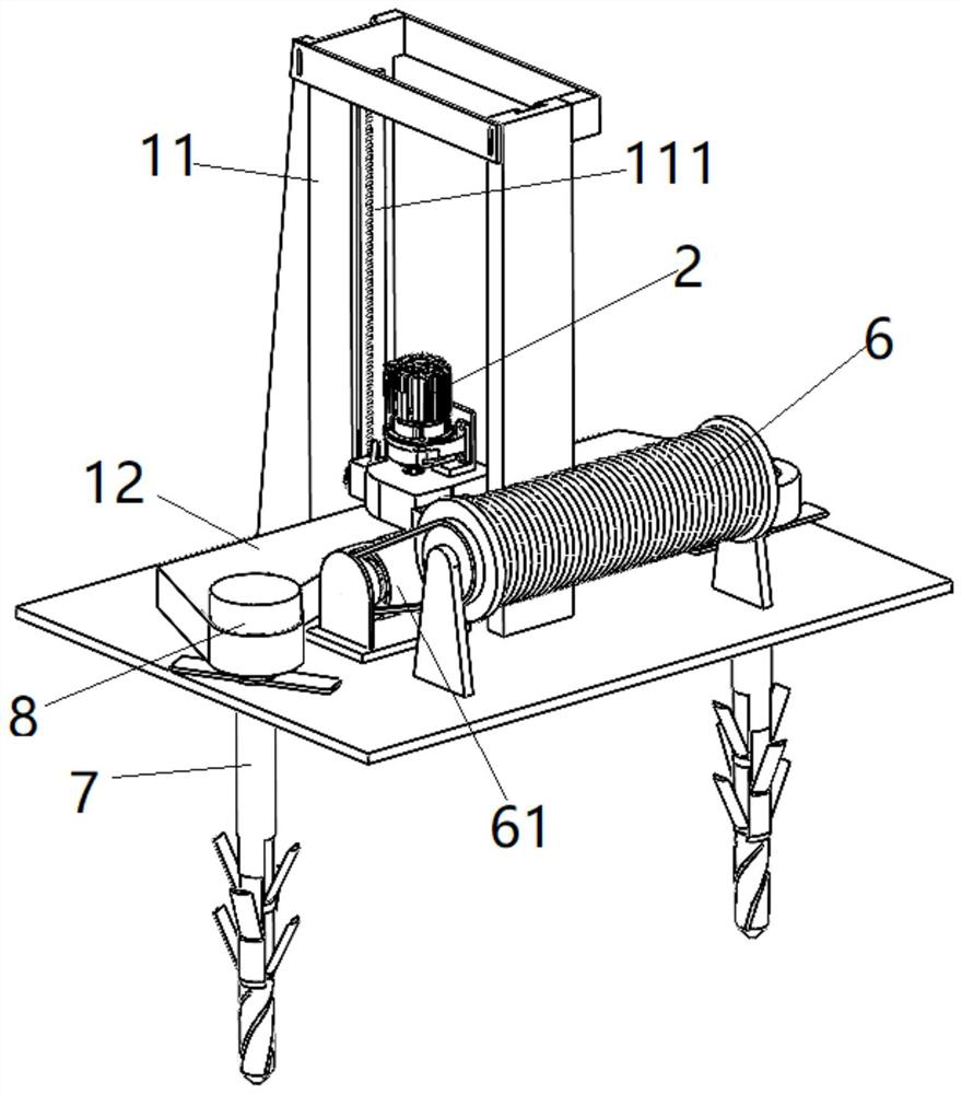
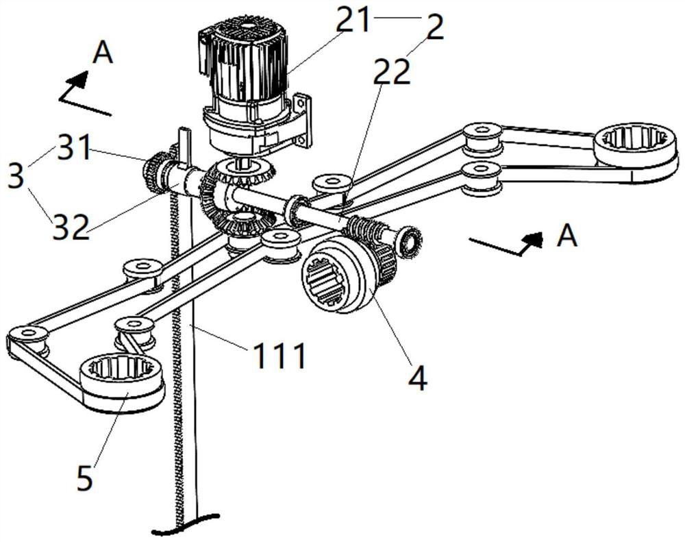
[0050] Place the device in a relatively safe location, install the two fixing mechanisms 7 on the second rotating group 5 on both sides of the housing 11 through the two third connecting pieces 8 respectively, and separate the limiting group 74 from the bayonet 711 , so that the first elastic member 75 is released, and a plurality of reinforcing plates 73 are unfolded, the driving group 2 is opened, and the driving member 21 drives the second rotating group 5 to move through the first shaft 22, thereby causing the two fixing mechanisms 7 to rotate. At this time, Move the first connecting piece 32 towards the direction close to the first shaft 22, and engage with the meshing hole in the helical gear on the first end of the first shaft 22, as attached Figure 4 As shown, the second shaft 31 can be coaxially and synchronously connected with the first ...


PUM


Abstract

The invention provides a rescue device for a water conservancy project. The rescue device comprises a bottom plate, a driving mechanism, a winder, a rope, a rescue suit and a fixing mechanism; the driving mechanism and the winder are both mounted on the bottom plate; one end of the rope is wound on the winder; the driving mechanism can be in driving connection with the winder; the fixing mechanism can be connected with the driving mechanism; the bottom plate is fixedly connected with the ground through the driving mechanism; the driving mechanism comprises a mounting frame, a shell, a driving set, a lifting set, a first rotating set and a second rotating set, wherein the driving set, the lifting set, the first rotating set and the second rotating set are all mounted in the shell; the first rotating set and the second rotating set are both in driving connection with the driving set; the lifting set can be in driving connection with the driving set and is driven by the driving set to drive the shell to ascend and descend in the height direction of the mounting frame; the first rotating set can be in driving connection with the winder; and the second rotating set can be in driving connection with the fixing mechanism. In general, the rescue device for the water conservancy project can be deployed rapidly and flexibly, so that the rescue efficiency is improved.

Description

technical field [0001] The present application relates to the field of water conservancy rescue equipment, in particular to a rescue device for water conservancy projects. Background technique [0002] Water conservancy projects are projects built to control and allocate natural surface water and groundwater to achieve the purpose of eliminating harm and promoting benefits. When tourists or pedestrians walk and play beside the river, unexpected accidents may cause tourists or pedestrians to fall. When entering the water, there may be certain hidden dangers due to the flow rate of the water, which will bring great difficulties to the rescuers. Therefore, the existing rescue devices will be bound to the rescuers through ropes, so that the rescuers have safety guarantees when they rescue. Some rescue devices are divided into portable mobile and fixed. The fixed method of the portable and mobile type is only provided by the gravity of the personnel on the shore. The danger of r...

Claims


Application Information

Patent Timeline
IPC IPC(8): B66D1/12B66D1/14B66D1/36B66D1/30B66D1/42B63C9/00
CPCB66D1/12B66D1/14B66D1/36B66D1/30B66D1/42B63C9/00
Inventor 韩伟郭建张波张怀成张克
Owner 韩伟
Learn More