Automatic stamping mechanism for stainless steel cover machining
A stainless steel, push mechanism technology, applied in printing, stamping and other directions, can solve problems such as affecting the imprinting accuracy and imprinting effect, and prone to slippage.
- Summary
- Abstract
- Description
- Claims
- Application Information
AI Technical Summary
Problems solved by technology
Method used
Image

Examples
Embodiment 1
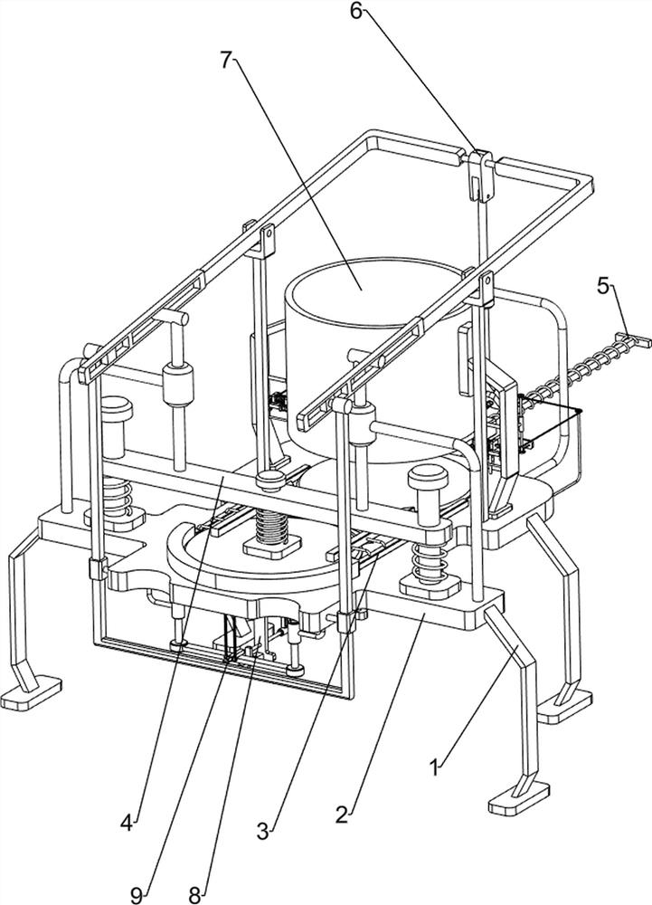
[0074] An automatic stamping mechanism for stainless steel cap processing, such as figure 1 As shown, it includes a bracket 1, a workbench 2, a stop bar 3, an embossing mechanism 4, and a push mechanism 5. A workbench 2 is connected between the tops of the four supports 1, and a stop bar 3 is arranged symmetrically on the front side of the top of the workbench 2. , The top of the workbench 2 is provided with an embossing mechanism 4, and the rear side of the workbench 2 is provided with a push mechanism 5.
[0075] When people need to process and seal the stainless steel cover, this automatic stamping mechanism can be used. First, the stainless steel cover is placed on the workbench 2 at the push mechanism 5, and then the push mechanism 5 is pushed forward, and the stainless steel cover is pushed to the Between the retaining rods 3, then let go to make the pushing mechanism 5 move backwards, and then press down on the imprinting mechanism 4, which will emboss the stainless ste...
Embodiment 2
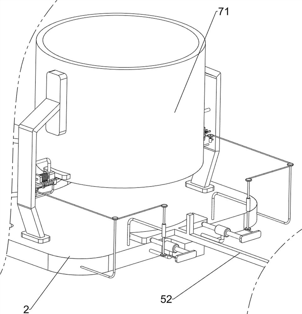
[0077] On the basis of Example 1, such as figure 2 and image 3 As shown, the embossing mechanism 4 includes a guide rod 41, an elastic pressing plate 42, an embossing assembly 43, a first guide sleeve 44, a pull column 45, a first rotary sleeve 46 and a first pull plate 47, and the top front side of the workbench 2 Both the left and right parts are provided with guide rods 41, and an elastic pressure plate 42 is slidably connected between the two guide rods 41. The middle part of the elastic pressure plate 42 is slidably provided with an embossing assembly 43, and the left and right parts on the front side of the top of the workbench 2 are equipped with The first guide sleeve 44, the first guide sleeve 44 is located at the outside of the guide rod 41, the left and right sides of the top of the elastic pressure plate 42 are provided with pull columns 45, the pull columns 45 are slidably connected with the first guide sleeve 44 on the same side, and the workbench 2 Both the l...
Embodiment 3
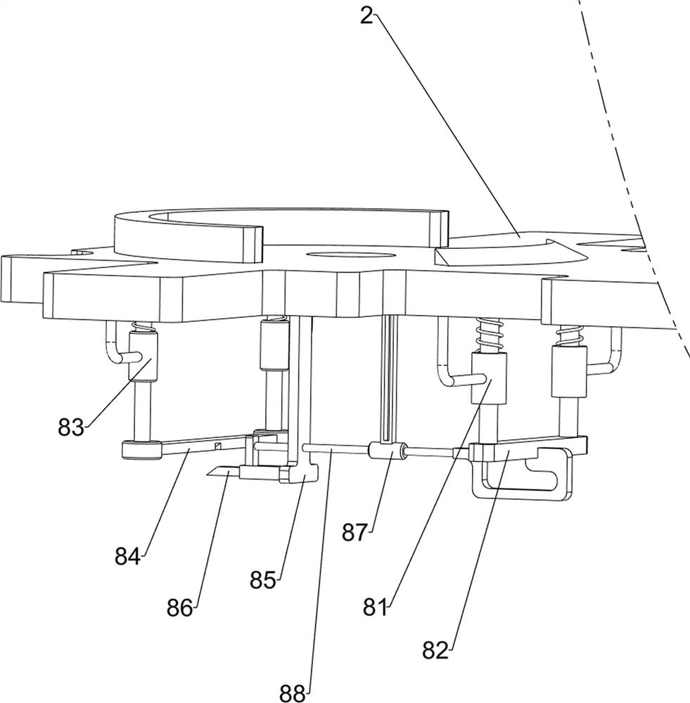
[0082] On the basis of Example 2, such as Figure 4-8 As shown, a lifting mechanism 6 is also included. The lifting mechanism 6 includes a third guide sleeve 61, a pressure column 62, a connecting plate 63, a fourth guide sleeve 64 and an elastic wedge block 65. The rear wall of the workbench 2 is provided with a third guide sleeve. Sleeve 61, two pieces of the first pull plate 47 rear sides are rotatably connected with connecting plate 63; A fourth guide sleeve 64 is provided on the front side of the top of the sleeve 51 , and an elastic wedge 65 is slidably provided in the top of the fourth guide sleeve 64 .
[0083] When the push plate 52 slides back to reset, the push plate 52 drives the elastic wedge 65 to slide backward along the fourth guide sleeve 64, and the elastic wedge 65 contacts and cooperates with the pressure column 62, thereby driving the pressure column 62 to slide along the third guide sleeve. The sleeve 61 slides upward, and the pressure column 62 drives t...
PUM
 Abstract
Description
Claims
Application Information
 - R&D
- Intellectual Property
- Life Sciences
- Materials
- Tech Scout
- Unparalleled Data Quality
- Higher Quality Content
- 60% Fewer Hallucinations
Browse by: Latest US Patents, China's latest patents, Technical Efficacy Thesaurus, Application Domain, Technology Topic, Popular Technical Reports.
© 2025 PatSnap. All rights reserved.Legal|Privacy policy|Modern Slavery Act Transparency Statement|Sitemap|About US| Contact US: help@patsnap.com