
Medical waste incineration, filtration and purification equipment

A technology for filtering and purifying medical waste, applied in incinerators, lighting and heating equipment, combustion methods, etc., can solve problems such as inability to realize automation, disease spread, and harm to physical and mental health

Pending Publication Date: 2021-05-18
黄付萍
View PDF9 Cites 0 Cited by
  • Summary
  • Abstract
  • Description
  • Claims
  • Application Information

AI Technical Summary

Problems solved by technology

[0002] Medical waste refers to direct or indirect infectious, toxic and other hazardous waste produced by medical institutions in medical treatment, prevention, health care and other related activities. These wastes contain a large number of bacterial viruses and have certain space pollution. The characteristics of acute virus infection and latent infection, if the management is not strengthened, discarded at will, and allowed to mix with household garbage and disperse into people's living environment, it will pollute the air, water, land, animals and plants, cause the spread of diseases, and seriously endanger people. physical and mental health, so we need to design a purification equipment
[0003] Patent application CN206695145U, with a publication date of 20171201, discloses a medical waste incineration device. A gap is provided on the fixing frame, and the bottom plate is inserted into the gap, so that the bottom plate can be pulled out from the bottom of the package. After the medical waste is incinerated, the bottom plate It can be pulled out from the bottom of the packaging body, allowing the residues obtained from medical waste incineration to fall directly through the ash discharge hole. The device has a simple structure and is easy to operate, but it needs to be taken in and out manually during operation, and cannot be automated.

Method used


Image

  • Medical waste incineration, filtration and purification equipment
  • Medical waste incineration, filtration and purification equipment
  • Medical waste incineration, filtration and purification equipment

Examples


Embodiment 1

[0069] A medical waste incineration filter purification equipment, such as figure 1 with figure 2 As shown, a base frame 1, a material holding mechanism 2 and an incineration mechanism 3 are included.

[0070]When people need to incinerate medical waste, they can use this medical waste incineration filter purification equipment. First, people put the medical waste in the material holding mechanism 2, and then start the material holding mechanism 2, and the material holding mechanism 2 pushes the medical waste to the On the lower side of the incineration mechanism 3, the incineration mechanism 3 incinerates the medical waste, and closes the material holding mechanism 2 when pushing is not required.

Embodiment 2

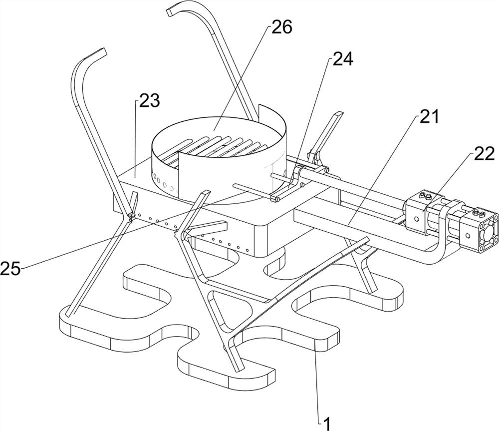
[0072] On the basis of Example 1, such as image 3 with Figure 4 As shown, the material holding mechanism 2 includes a fixed plate 21, a cylinder 22, a mounting frame 23, a push block 24, a connecting column 25 and a hopper 26, the base frame 1 is connected with a mounting frame 23, and the mounting frame 23 rear portion is provided with a mounting plate 21. A cylinder 22 is installed at the rear of the fixed plate 21, and the telescopic rod of the cylinder 22 is connected with a push block 24. The front side of the push block 24 is evenly provided with three connecting columns 25, and the front part between the three connecting columns 25 is connected with a hopper 26 , The hopper 26 is slidably connected with the mounting frame 23 .

[0073] First, people put medical waste in the hopper 26, and then start the cylinder 22. The telescopic rod of the cylinder 22 drives the push block 24 and the connecting column 25 to reciprocate back and forth, thereby driving the hopper 26 ...

Embodiment 3

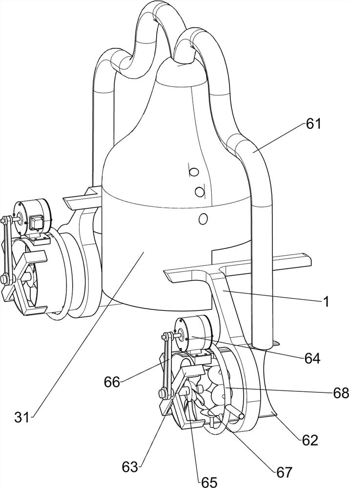
[0077] On the basis of Example 2, such as Figure 5-8 As shown, a fire valve mechanism 4 is also included. The fire valve mechanism 4 includes a first elastic assembly 41, a moving block 42, a top block 43, a slide bar 44 and a valve block 45. Top block 43, the upper side of the first fixed block 32 is slidingly provided with a first elastic assembly 41, the rear part between the two first elastic assemblies 41 is connected with a moving block 42, and the rear part of the moving block 42 cooperates with the front part of the top block 43 , The upper side of the middle part of the moving block 42 is provided with a slide bar 44, the rear part of the slide bar 44 is connected with a valve block 45, and the valve block 45 is slidably connected with the catheter tube 34 front side.

[0078] The reciprocating movement of the hopper 26 drives the top block 43 back and forth. When the hopper 26 drives the top block 43 to move forward to the bottom of the incinerator 31, the top block...


PUM


Abstract

The invention relates to purification equipment, and especially relates to medical waste incineration, filtration and purification equipment. The invention provides automatic medical waste incineration, filtration and purification equipment integrating material containing, incineration and dust falling. The medical waste incineration, filtration and purification equipment comprises a material containing mechanism and an incineration mechanism, wherein the material containing mechanism is arranged at the middle part of a base frame; and the incineration mechanism is connected between the base frame and the material containing mechanism. According to the invention, a material containing hopper reciprocates front and back, and when the material containing hopper drives medical waste to move forwards to a position below the incineration mechanism, the incineration mechanism incinerates the medical waste; and combustible liquid enters a liquid guide pipe from a liquid storage box and then drips onto the medical waste, so that the medical waste is burnt, and the effect of burning the medical waste is realized.

Description

technical field [0001] The invention relates to a purification device, in particular to a medical waste incineration filtration purification device. Background technique [0002] Medical waste refers to direct or indirect infectious, toxic and other hazardous waste produced by medical institutions in medical treatment, prevention, health care and other related activities. These wastes contain a large number of bacterial viruses and have certain space pollution. The characteristics of acute virus infection and latent infection, if the management is not strengthened, discarded at will, and allowed to mix with household garbage and disperse into people's living environment, it will pollute the air, water, land, animals and plants, cause the spread of diseases, and seriously endanger people. Physical and mental health, so we need to design a purification equipment. [0003] Patent application CN206695145U, with a publication date of 20171201, discloses a medical waste incinerat...

Claims


Application Information

Patent Timeline
IPC IPC(8): F23G7/00F23G5/44F23G5/12F23J1/00F23J15/04
CPCF23G7/00F23G5/444F23G5/12F23J1/00F23J15/04F23G2204/103F23G2205/14F23G2209/20F23J2217/50F23J2700/003
Inventor 黄付萍
Owner 黄付萍
Learn More