


Quick Research
Generate reliable direction feasibility study reports for your R&D in just a few steps.

Technical Q&A
Discover and master advanced knowledge NOW. Basics, ideas, possibilities, all at once.

Find Solutions
As an expert in R&D theories, this can generate solutions to your technical problems instantly.

Evaluate Feasibility
Analyze your overall solution with one click, know your potential R&D risks in advance.

Monitor Landscape
Get weekly tech updates, stay abreast of the latest tech innovations and key insights.
Lubrication control system and method for numerical control machine tool and capable of automatically adjusting lubrication according to needs
A numerical control machine tool and automatic adjustment technology, applied in the field of numerical control lathes, can solve the problem of not being able to provide lubrication for fixtures, and achieve the effect of maintaining on-demand supply, improving lubricating oil, and avoiding complex processes
- Summary
- Abstract
- Description
- Claims
- Application Information
AI Technical Summary
Problems solved by technology
Method used
Image

Examples
Embodiment 1
[0034] The method for automatically adjusting the lubricating control system of a CNC machine tool according to needs, the specific steps are as follows:
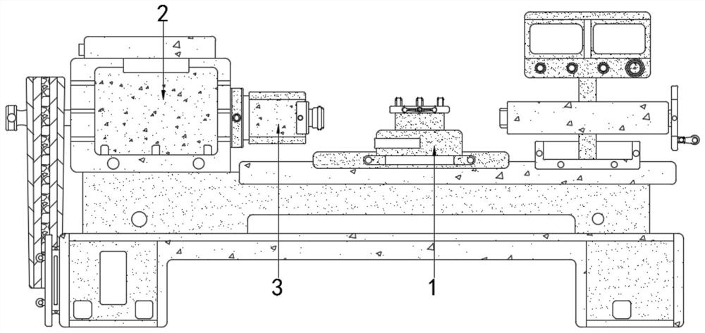
[0035] S1. The pre-user fixes the workpiece on the right side of the holder 3, and then energizes the motor so that the output shaft drives the rotating shaft 4 and the telescopic rod 501 to rotate at a speed of 200r / min;
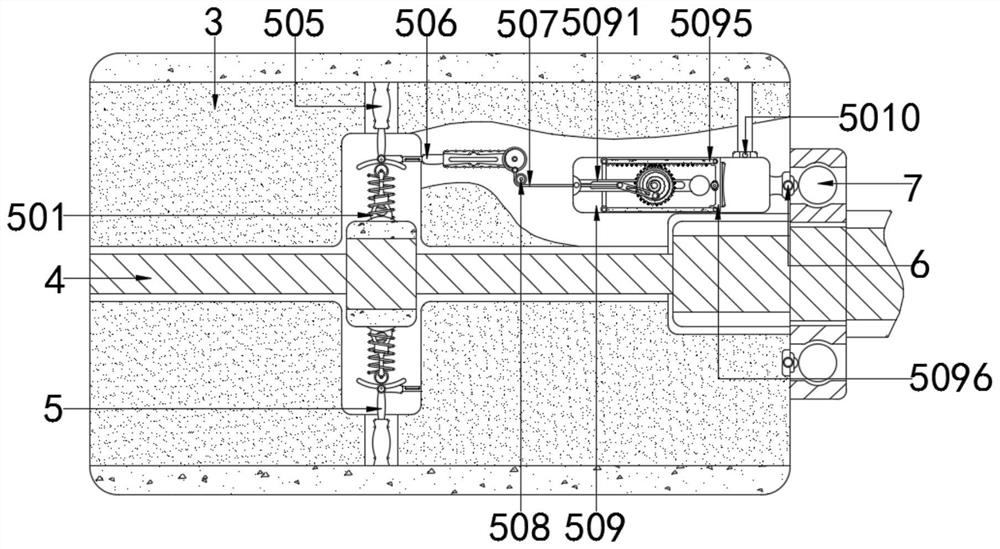
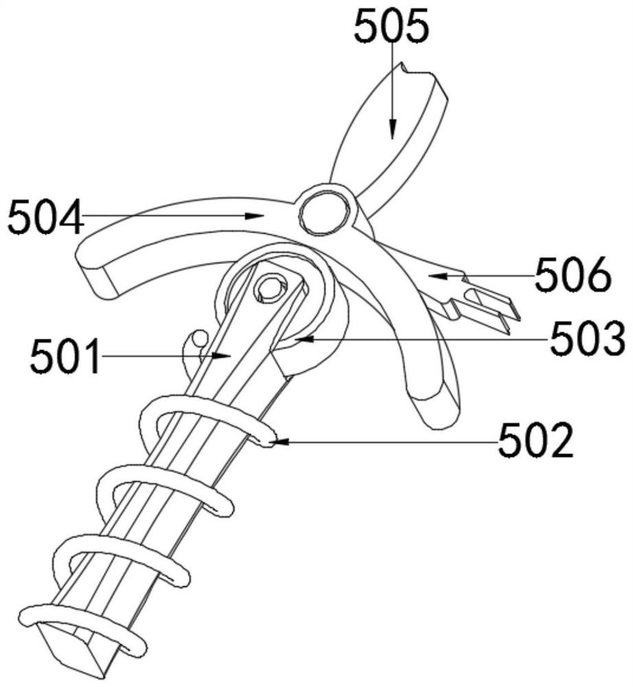
[0036] S2. When the rotating shaft 4 changes from a low speed to a high speed, the eccentricity of the rotating shaft 4 increases, and then the telescopic rod 501 drives the pressure wheel 503 to move outward with the assistance of the return spring 502, and the movement of the pressure wheel 503 gradually pulls and resets as it rotates The spring 502 simultaneously drives the arc plate 504 to move;
[0037] S3. Immediately after the arc plate 504 is moving, the negative pressure rod 505 is squeezed to drive the joint rod 506 to rotate. The rotation of the joint rod 506 cooperates with the fixed pulley 5...
Embodiment 2
[0042] The method for automatically adjusting the lubricating control system of a CNC machine tool according to needs, the specific steps are as follows:
[0043] S1. The pre-user fixes the workpiece on the right side of the holder 3, and then energizes the motor so that the output shaft drives the rotating shaft 4 and the telescopic rod 501 to rotate at a speed of 300r / min;
[0044] S2. When the rotating shaft 4 changes from a low speed to a high speed, the eccentricity of the rotating shaft 4 increases, and then the telescopic rod 501 drives the pressure wheel 503 to move outward with the assistance of the return spring 502, and the movement of the pressure wheel 503 gradually pulls and resets as it rotates The spring 502 simultaneously drives the arc plate 504 to move;
[0045] S3. Immediately after the arc plate 504 is moving, the negative pressure rod 505 is squeezed to drive the joint rod 506 to rotate. The rotation of the joint rod 506 cooperates with the fixed pulley 5...
Embodiment 3
[0050] The method for automatically adjusting the lubricating control system of a CNC machine tool according to needs, the specific steps are as follows:
[0051] S1. The pre-user fixes the workpiece on the right side of the holder 3, and then energizes the motor so that the output shaft drives the rotating shaft 4 and the telescopic rod 501 to rotate at a speed of 400r / min;
[0052] S2. When the rotating shaft 4 changes from a low speed to a high speed, the eccentricity of the rotating shaft 4 increases, and then the telescopic rod 501 drives the pressure wheel 503 to move outward with the assistance of the return spring 502, and the movement of the pressure wheel 503 gradually pulls and resets as it rotates The spring 502 simultaneously drives the arc plate 504 to move;
[0053] S3. Immediately after the arc plate 504 is moving, the negative pressure rod 505 is squeezed to drive the joint rod 506 to rotate. The rotation of the joint rod 506 cooperates with the fixed pulley 5...
PUM
 Abstract
Description
Claims
Application Information
 - R&D Engineer
- R&D Manager
- IP Professional
- Industry Leading Data Capabilities
- Powerful AI technology
- Patent DNA Extraction
Browse by: Latest US Patents, China's latest patents, Technical Efficacy Thesaurus, Application Domain, Technology Topic, Popular Technical Reports.
© 2024 PatSnap. All rights reserved.Legal|Privacy policy|Modern Slavery Act Transparency Statement|Sitemap|About US| Contact US: help@patsnap.com