
Novel unmanned aerial vehicle handle and using method thereof

A technology of drone handles and drones, applied in the field of drones, can solve the problems of complicated operation of drone handles and inconvenient use for novices, and achieve the effect of avoiding out-of-control phenomena, avoiding bumps, and reducing operational difficulty

Active Publication Date: 2021-07-27
宁波五浪体育文化传媒有限公司
View PDF10 Cites 1 Cited by
  • Summary
  • Abstract
  • Description
  • Claims
  • Application Information

AI Technical Summary

Problems solved by technology

However, the UAV handle of this control method is more complicated to operate, mainly relying on the control feel and proficiency of the controller to maintain the stability of the UAV flight, which is not easy for novices to use

Method used


Image

  • Novel unmanned aerial vehicle handle and using method thereof
  • Novel unmanned aerial vehicle handle and using method thereof
  • Novel unmanned aerial vehicle handle and using method thereof

Examples


Embodiment 1

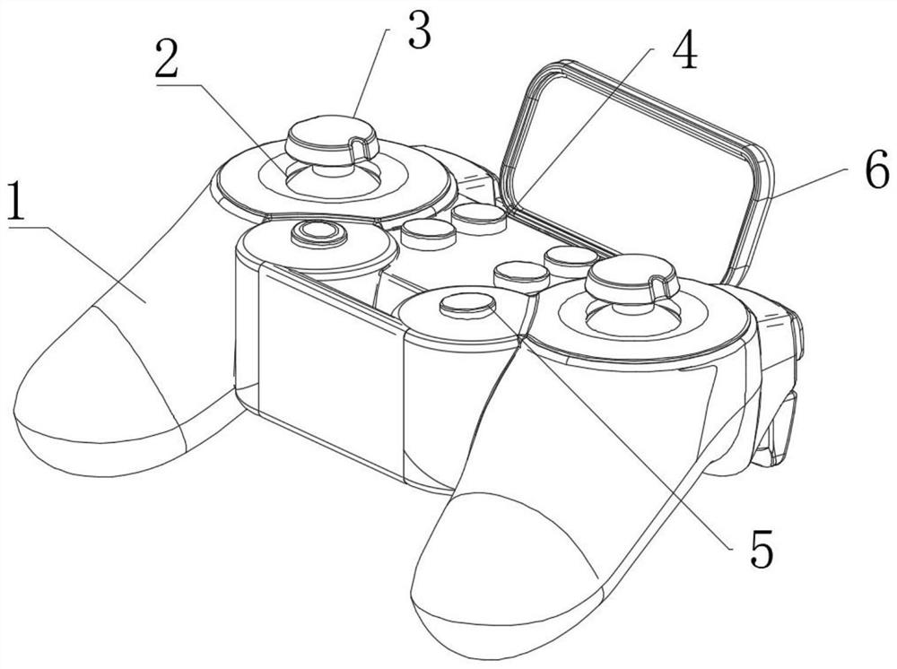
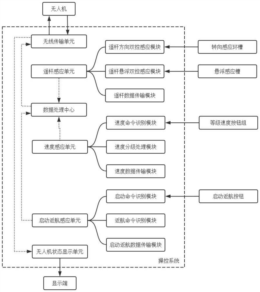
[0053] see Figure 1-10 , a new type of UAV handle, including a control handle 1, a pair of remote rod ball grooves 2 are provided at the upper end of the control handle 1, a remote rod control component 3 is arranged in the remote rod ball groove 2, and a remote rod control assembly 3 is installed on the upper end of the control handle 1. The start return button 5 on the rear side of the control unit 3, the upper end of the control handle 1 is provided with a grade speed button group 4, the grade speed button group 4 is located between the two joystick control assemblies 3, and the joystick control module 3 is provided with a joystick limiter. Bit component 7, a UAV controller is installed in the control handle 1, and a control system is arranged in the UAV controller; please refer to Figure 4-Figure 8 , the remote rod control assembly 3 includes a remote rod control sensing ball 301, the remote rod control sensing ball 301 is rotationally connected in the remote rod ball gr...

Embodiment 2

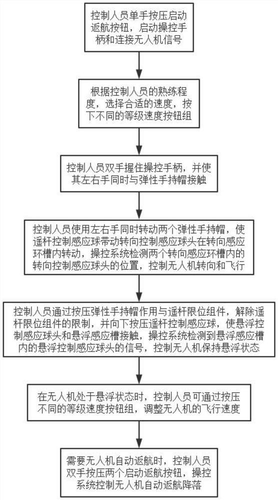
[0064] see Figure 1-10 , where the same or corresponding components as those in Embodiment 1 use the corresponding reference numerals as in Embodiment 1, and for the sake of simplicity, only the differences from Embodiment 1 will be described below. The difference between this embodiment 2 and embodiment 1 is: please refer to figure 2 , a method for using a novel drone handle, comprising the steps of:

[0065] S1. The controller presses the start return button 5 with one hand, starts the control handle 1 and connects to the UAV signal;

[0066] S2. According to the proficiency of the controller, select the appropriate speed, and press the different grade speed button group 4;

[0067] S3. The controller holds the control handle 1 with both hands, and makes his left and right hands contact with the elastic hand cap 306 at the same time;

[0068] S4. The controller rotates the two elastic hand-held caps 306 with the left and right hands at the same time, so that the remote ...


PUM


Abstract

The invention discloses a novel unmanned aerial vehicle handle and a using method thereof, and belongs to the field of unmanned aerial vehicles, the novel unmanned aerial vehicle handle comprises a control handle, a pair of rocker ball grooves are formed in the upper end of the control handle, and rocker control assemblies are arranged in the rocker ball grooves; the upper end of the control handle is provided with a starting return button located in the rear sides of the rocker control assemblies, the upper end of the control handle is provided with a grade speed button set, the grade speed button set is located between the two rocker control assemblies, and by arranging the two rocker control assemblies, a controller must control the unmanned aerial vehicle to fly with the two hands; the control stability of the unmanned aerial vehicle is effectively improved, the out-of-control phenomenon caused by too large single-hand control amplitude is effectively avoided, the operation difficulty of the control handle is reduced, constant control over the flight speed of the unmanned aerial vehicle is effectively achieved through the grade speed button set, the control difficulty of the unmanned aerial vehicle is reduced, operation is easy and convenient, and use of a green hand is facilitated.

Description

technical field [0001] The present invention relates to the field of unmanned aerial vehicles, and more specifically, relates to a novel unmanned aerial vehicle handle and its usage method. Background technique [0002] Unmanned aircraft, referred to as "unmanned aerial vehicle", or "UAV" in English, is an unmanned aircraft that is controlled by radio remote control equipment and its own program control device, or is completely or intermittently operated autonomously by an on-board computer. According to the application field, UAV can be divided into military and civilian. In terms of military use, UAVs are divided into reconnaissance aircraft and target aircraft. In terms of civilian use, drones + industry applications are the real rigid needs of drones; currently, they are used in aerial photography, agriculture, plant protection, micro selfies, express delivery, disaster relief, wildlife observation, infectious disease monitoring, surveying and mapping, news reports, pow...

Claims


Application Information

Patent Timeline
Patent Type & Authority Applications(China)
IPC IPC(8): G05G1/10
CPCG05G1/10
Inventor 李珊珊
Owner 宁波五浪体育文化传媒有限公司
Learn More