
Windproof assembly for optical fiber fusion splicer and optical fiber fusion splicer

A technology of optical fiber fusion splicer and fusion splicer, which is applied in the direction of optical components, light guides, optics, etc., can solve the problems of the guide mechanism losing its guiding and limiting functions, reducing the quality of fusion splicing, and large diameter difference, etc., to achieve overall height reduction and improve splicing High-quality, high-fit effect

Inactive Publication Date: 2021-07-27
季锋
View PDF0 Cites 0 Cited by
  • Summary
  • Abstract
  • Description
  • Claims
  • Application Information

AI Technical Summary

Problems solved by technology

However, due to the large variety of insulating layers and the large difference in diameter, when the insulating layer is too thick or too thin, the guiding mechanism will lose its guiding and limiting functions, thereby reducing the welding quality.

Method used


Image

  • Windproof assembly for optical fiber fusion splicer and optical fiber fusion splicer
  • Windproof assembly for optical fiber fusion splicer and optical fiber fusion splicer
  • Windproof assembly for optical fiber fusion splicer and optical fiber fusion splicer

Examples


Embodiment Construction

[0041] In order to make the purpose, technical solutions and advantages of the embodiments of the present invention clearer, the technical solutions in the embodiments of the present invention will be clearly and completely described below in conjunction with the accompanying drawings in the embodiments of the present invention. Obviously, the described embodiments It is a part of embodiments of the present invention, but not all embodiments. Based on the embodiments of the present invention, all other embodiments obtained by persons of ordinary skill in the art without making creative efforts belong to the protection scope of the present invention.

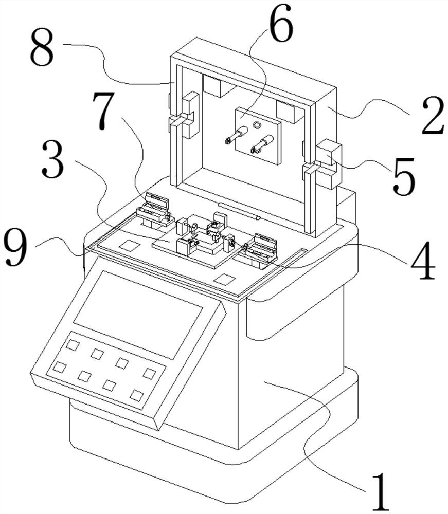
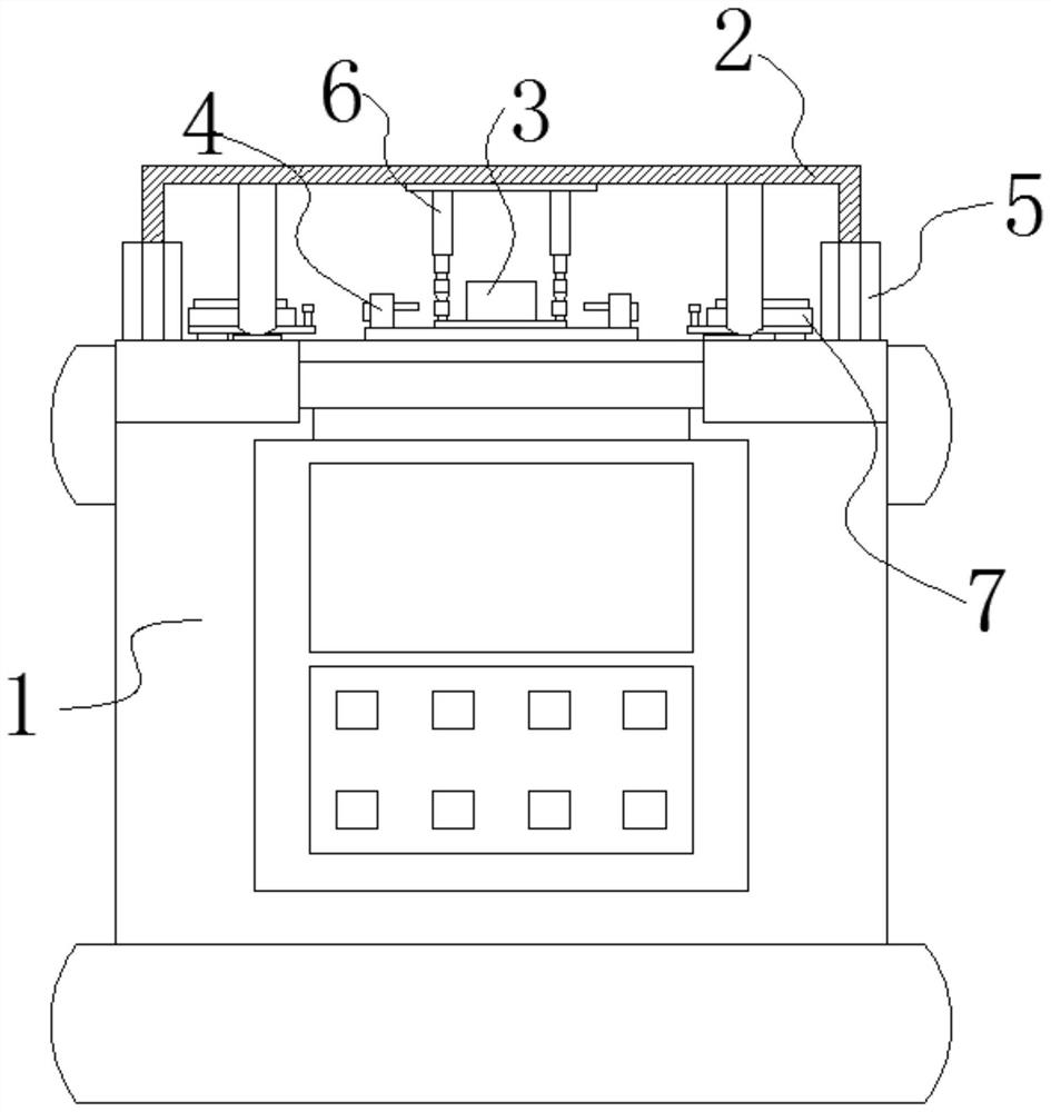
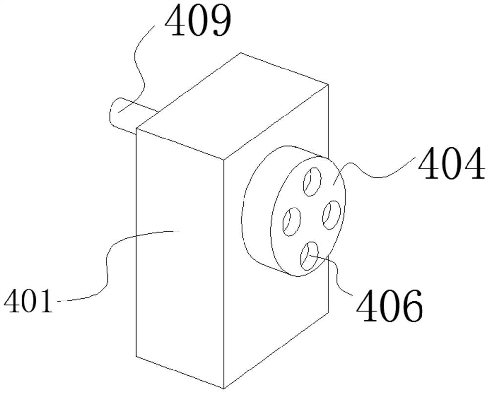
[0042] An embodiment of the present invention provides an optical fiber fusion splicer. The optical fiber fusion splicer includes a fusion splicer body 1 , a windproof assembly, a discharge module 3 and a wire assembly 4 . Exemplary, such as figure 1 and figure 2 As shown, the discharge module 3 is fixedly installed on the to...


PUM

PropertyMeasurementUnit
lengthaaaaaaaaaa

Abstract

The invention relates to the technical field of photoelectric communication equipment manufacturing, in particular to a windproof assembly for an optical fiber fusion splicer and the optical fiber fusion splicer. The optical fiber fusion splicer comprises a fusion splicer body, a windproof assembly, a discharge module and a wire assembly. The discharge module is fixedly mounted at the top of the welding machine body, and the discharge module is electrically connected with a control part of the welding machine body through an electric wire; two shells of the wire assembly are both fixedly installed on the base of the discharging module, and the two shells of the wire assembly are symmetrically arranged at the two sides of the central axis of the discharging module; and the output end of the wire assembly and the welding part of the discharging module are located on the same horizontal plane. The windproof assembly comprises a windproof cover, a wire arranging assembly and a wire pressing assembly; and the windproof cover is hinged to the edge of one side of the top of the welding machine body. According to the invention, the compatibility of the welding machine is improved, and the welding quality is improved.

Description

technical field [0001] The invention belongs to the technical field of photoelectric communication equipment manufacturing, and in particular relates to a windproof component for an optical fiber fusion splicer and an optical fiber fusion splicer. Background technique [0002] The work content of the optical fiber fusion splicer is mainly to connect two groups of optical fibers to ensure the normal transmission of digital information. The flatness error of the optical fiber after fusion splicing by the optical fiber fusion splicer is usually calculated in nanometers, which is a very high-end precision instrument in the field of optical communication. [0003] According to different occasions and different environmental requirements, optical fibers are roughly divided into 850 nanometers, 980 nanometers, 1310 nanometers, 1490 nanometers and 1550 nanometers according to the wavelength. The outer insulating layer of optical fiber can be roughly divided into two types: jumper w...

Claims


Application Information

Patent Timeline
Patent Type & Authority Applications(China)
IPC IPC(8): G02B6/255
CPCG02B6/2553G02B6/2555
Inventor 季锋
Owner 季锋
Learn More