Laser die cutting equipment convenient to feed

A laser die-cutting and equipment technology, applied in laser welding equipment, welding equipment, metal processing equipment, etc., can solve the problems of plate deviation, low safety, error, etc., to increase stability, facilitate feeding, and facilitate emissions. Effect

Active Publication Date: 2021-07-27
江苏众旺鑫智能设备有限公司
View PDF10 Cites 0 Cited by
  • Summary
  • Abstract
  • Description
  • Claims
  • Application Information

AI Technical Summary

Problems solved by technology

[0003] However, the current laser die-cutting machine will produce a small amount of debris when cutting the rough PCB board. The laser die-cutting equipment is not equipped with a mechanism to clean up the debris. The debris on the laser die-cutting equipment for a long time There is a lot of chip accumulation, which is inconvenient to place the PCB board, and changes the flatness of the placement, which will cause errors during cutting and affect the accuracy of cutting; and when cutting a rough PCB board, the PCB board directly Placed on the surface of the workbench, the staff relies on the palm to press the plate when cutting, and the plate is prone to slight deviation during cutting, which affects the integrity of the cutting and has low safety

Method used


Image

  • Laser die cutting equipment convenient to feed
  • Laser die cutting equipment convenient to feed
  • Laser die cutting equipment convenient to feed

Examples


Embodiment Construction

[0030] In order to make the technical means, creative features, goals and effects achieved by the present invention easy to understand, the present invention will be further described below in conjunction with specific embodiments.

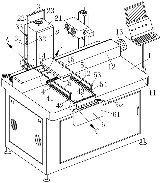
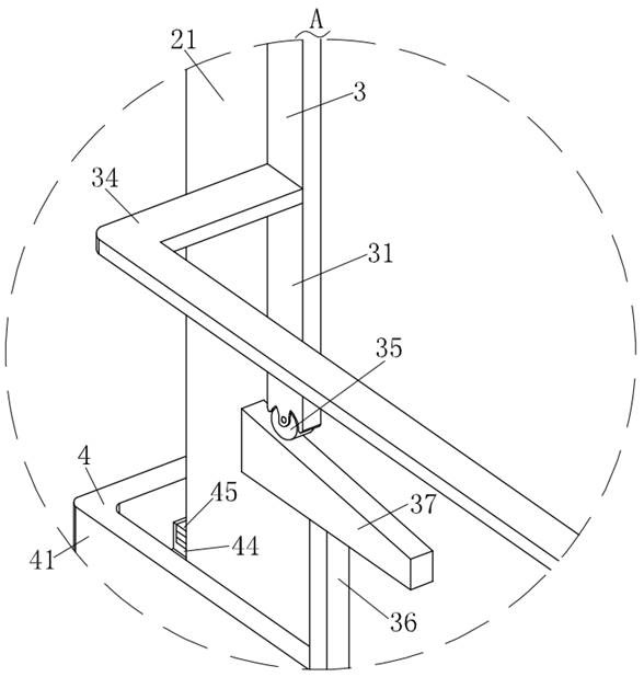
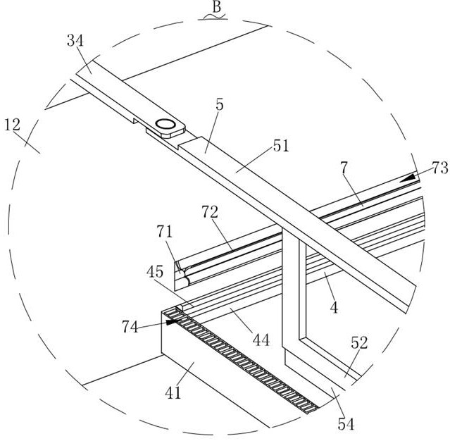
[0031] Such as Figure 1-Figure 8 As shown, a laser die-cutting device for convenient feeding according to the present invention includes a main body mechanism 1, which is used to support the overall mechanism and place the boards to be cut. The discharge mechanism 2 of the board, the discharge mechanism is provided with a discharge mechanism 4 for fast feeding, and the discharge mechanism 4 is provided with a linkage mechanism 3 located on both sides of the discharge mechanism 2, and the linkage mechanism 3 is installed with a pressing mechanism 5 for pressing the PCB board to be cut, and the main mechanism 1 is provided with a receiving mechanism 6 for collecting debris during cutting. The pneumatic mechanism 7 that is engaged between the mater...


PUM


Abstract

The invention relates to the technical field of laser die-cutting equipment, in particular to laser die cutting equipment convenient to feed. The laser die cutting equipment comprises a main body mechanism, and a storing mechanism for storing PCBs is mounted on the main body mechanism for supporting the whole mechanism and placing plates to be cut. a discharging mechanism used for rapid feeding is arranged on the storing mechanism, linkage mechanisms located on the two sides of the storing mechanism are arranged on the discharging mechanism, pressing mechanisms used for pressing PCBs needing to be cut are installed on the linkage mechanisms, a collecting mechanism used for collecting chippings generated during cutting is arranged on the main body mechanism, and a pneumatic mechanism which is meshed with the discharging mechanism and is used for cleaning cut chippings is mounted on the main body mechanism; According to the laser die cutting equipment, PCBs can be stored through the storing mechanism, the discharging mechanism sliding on the storing mechanism can be pulled when the PCBs are cut, the PCBs stacked in the storing mechanism can be rapidly pushed out, and feeding is convenient.

Description

technical field [0001] The invention relates to the technical field of laser die-cutting equipment, in particular to a laser die-cutting device for convenient feeding. Background technique [0002] The die-cutting process can make printed matter or other paper products into a die-cutting knife plate for cutting according to the pre-designed graphics, so that the shape of the printed matter is no longer limited to straight edges and right angles. Laser die-cutting is controlled by a computer for laser cutting. The cutting graphic design can be completed on the computer, and various graphic parameter settings are automatically generated based on software. When cutting some paper and plastic objects, a laser die-cutting machine will be used. [0003] However, the current laser die-cutting machine will produce a small amount of debris when cutting the rough PCB board. The laser die-cutting equipment is not equipped with a mechanism to clean up the debris. The debris on the laser...

Claims


Application Information

Patent Timeline
Patent Type & Authority Applications(China)
IPC IPC(8): B23K26/38B23K26/16B23K26/70
CPCB23K26/16B23K26/38B23K26/702
Inventor 蒋仁安
Owner 江苏众旺鑫智能设备有限公司
Why Eureka
Try Eureka