Eureka AIR delivers breakthrough ideas for toughest innovation challenges, trusted by R&D personnel around the world.

Line protection device

A line protection and wire technology, which is applied in the field of data lines, can solve problems such as the inability to realize emergency circuit breaks, and achieve the effect of protection

Active Publication Date: 2021-07-23
XIEXUN ELECTRONICS JI AN
View PDF12 Cites 0 Cited by
  • Summary
  • Abstract
  • Description
  • Claims
  • Application Information

AI Technical Summary

Problems solved by technology

[0002] The connection of existing lines cannot realize emergency disconnection in case of external collision

Method used


Image

  • Line protection device
  • Line protection device

Examples


Embodiment Construction

[0014] The following will clearly and completely describe the technical solutions in the embodiments of the present invention with reference to the accompanying drawings in the embodiments of the present invention. Obviously, the described embodiments are only some, not all, embodiments of the present invention. Based on the embodiments of the present invention, all other embodiments obtained by persons of ordinary skill in the art without making creative efforts belong to the protection scope of the present invention.

[0015] Please refer to the figure, the present invention provides a technical solution:

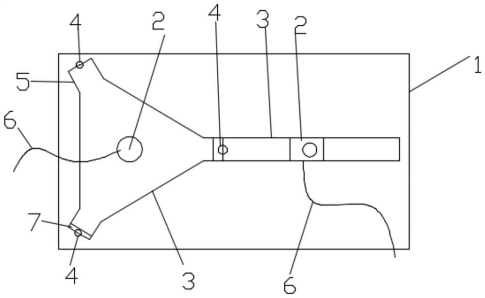
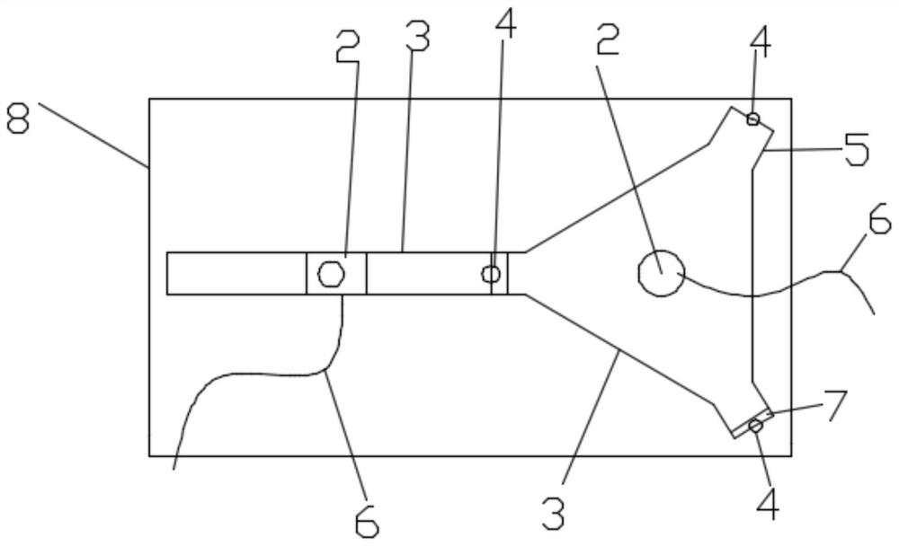
[0016] A line protection device, comprising a base plate 1, a rotating shaft 2, a triangular block 3, a contact point 4, a rectangular block 5, a wire 6, a special layer 7, and a vertical plate 8, characterized in that: the upper end surface of the base plate 1 passes through the rotating shaft 2. There is a flat triangular block 3 installed in rotation; the three corners...


PUM


Abstract

The invention discloses a line protection device, which comprises a bottom plate 1, a rotating shaft 2, a triangular block 3, a contact 4, rectangular blocks 5, a wire 6, a special layer 7 and a vertical plate 8, wherein the upper end surface of the bottom plate 1 is rotationally provided with the flat triangular block 3 through the rotating shaft 2; the three corners of the triangular block 3 are formed by rectangular blocks 5; a contact 4 is arranged on one side, far away from the triangular block 3, of each rectangular block 5; each contact 4 is electrically connected with the wire 6 through the rotating shaft 2; and a vertical plate 8 is vertically arranged on one side of the bottom plate 1.

Description

technical field [0001] The invention relates to the field of data lines, in particular to a line protection device. Background technique [0002] The connection of the existing lines cannot realize emergency disconnection in the event of an external collision. Contents of the invention [0003] The purpose of the present invention is to provide a line protection device to solve the problems raised in the background art above. [0004] To achieve the above object, the present invention provides the following technical solutions: [0005] The invention provides a technical solution: [0006] A line protection device, comprising a base plate 1, a rotating shaft 2, a triangular block 3, a contact point 4, a rectangular block 5, a wire 6, a special layer 7, and a vertical plate 8, characterized in that: the upper end surface of the base plate 1 passes through the rotating shaft 2. There is a flat triangular block 3 installed in rotation; the three corners of the triangular b...

Claims


Application Information

Patent Timeline
IPC IPC(8): H01H35/14H01H37/02H01H37/36H01H37/76
CPCH01H35/144H01H35/141H01H37/02H01H37/76H01H37/36
Inventor 罗南生宋明杨江韦万和
Owner XIEXUN ELECTRONICS JI AN
Why Eureka
Eureka Blog
Learn More