
Cluster unmanned aerial vehicle flight field magnetic interference detection method and device, medium and terminal

A technology of interference detection and unmanned aerial vehicle, applied in the direction of electrical/magnetic detection for logging records, can solve the problems of inability to detect interference, estimation error of attitude and speed, and calculation error of heading angle, etc. Ensure normal takeoff, reduce losses, and avoid the effect of position drift

Pending Publication Date: 2021-07-23
一飞(海南)科技有限公司
View PDF6 Cites 1 Cited by
  • Summary
  • Abstract
  • Description
  • Claims
  • Application Information

AI Technical Summary

Problems solved by technology

When there is magnetic field interference in the environment where the UAV is placed, there is a large error in the calculation of the heading angle, which affects the estimation of the attitude and speed, and there is also a large error, which causes the drift of the UAV position.
[0008] (2) Cluster drones often need to be placed densely when they take off, and there are often objects such as steel structures and pipes that generate strong magnetic fields under the placement site, which will seriously interfere with the geomagnetic sensor of the drone.
Drones with a single geomagnetic sensor cannot detect such disturbances
Moreover, since cluster drones are usually small in size and the surrounding magnetic fields are generally similar, it is impossible to detect such magnetic field interference by comparing the data of multiple geomagnetic sensors.

Method used


Image

  • Cluster unmanned aerial vehicle flight field magnetic interference detection method and device, medium and terminal
  • Cluster unmanned aerial vehicle flight field magnetic interference detection method and device, medium and terminal
  • Cluster unmanned aerial vehicle flight field magnetic interference detection method and device, medium and terminal

Examples


Embodiment Construction

[0039] In order to make the object, technical solution and advantages of the present invention more clear, the present invention will be further described in detail below in conjunction with the examples. It should be understood that the specific embodiments described here are only used to explain the present invention, not to limit the present invention.

[0040] Aiming at the problems existing in the prior art, the present invention provides a method and device for detecting magnetic interference in the flying field of cluster drones. The present invention will be described in detail below in conjunction with the accompanying drawings.

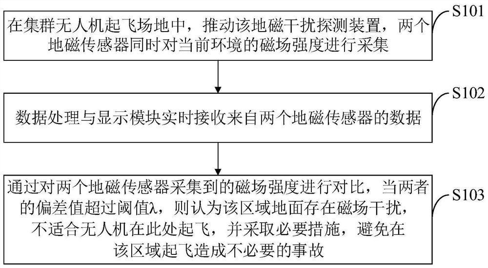
[0041] Such as figure 1 As shown, the method for detecting magnetic interference at the flight site of cluster drones provided by the embodiment of the present invention includes the following steps:

[0042] S101, push the geomagnetic interference detection device in the cluster UAV take-off site, and the two geomagnetic sensors simultaneous...


PUM


Abstract

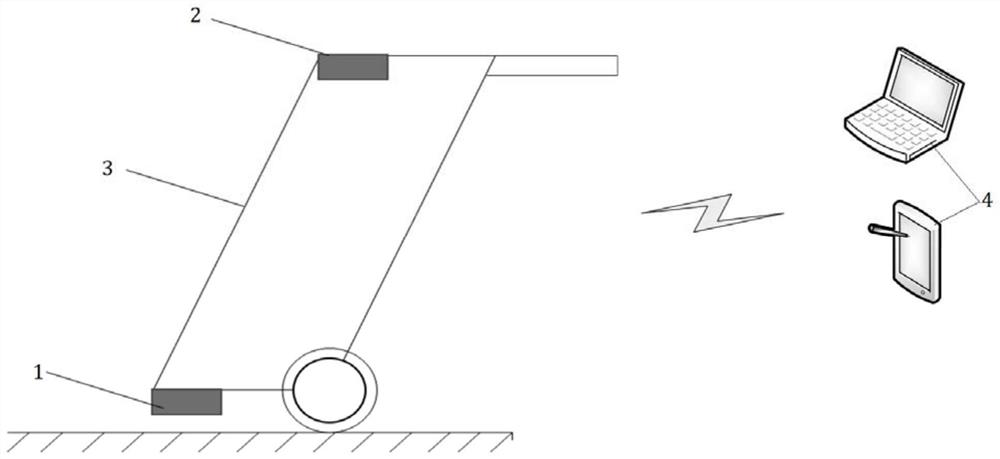
The invention belongs to the technical field of unmanned aerial vehicles, and discloses a cluster unmanned aerial vehicle flight field magnetic interference detection method and device, a medium and a terminal, and the cluster unmanned aerial vehicle flight field magnetic interference detection device comprises a geomagnetic field acquisition device and a data processing and display module. The geomagnetic field acquisition device comprises two geomagnetic sensors capable of acquiring environmental magnetic field intensity and a fixed connection device for fixing the two geomagnetic sensors in the same direction; the first geomagnetic sensor is fixed below the fixed connection device, and the distance from the first geomagnetic sensor to the ground is not more than 10cm; the second geomagnetic sensor is fixed above the fixed connection device and is 1m away from the ground; and the data processing and display module is used for collecting the geomagnetic field data sent by the acquisition device, processing the geomagnetic field data in real time and displaying a result on a terminal. According to the method, whether geomagnetic interference exists on the ground of the take-off site of the cluster unmanned aerial vehicle can be effectively judged, and unnecessary loss is avoided.

Description

technical field [0001] The invention belongs to the technical field of unmanned aerial vehicles, and in particular relates to a method, device, medium and terminal for detecting magnetic interference in a cluster unmanned aerial vehicle flight site. Background technique [0002] At present, drones that use geomagnetic sensors for navigation may experience position drift and unstable attitude during take-off when there is magnetic field interference in the placement environment. In severe cases, it will cause the aircraft to lose control or even explode. [0003] At present, most drones use geomagnetic sensors to calculate the heading angle, or use the fusion of geomagnetic sensors and inertial sensors to calculate the attitude. The geomagnetic sensor indicates the direction by detecting the geomagnetic field. Since the geomagnetic field is very weak, it is easily interfered by metal objects or electromagnetic equipment. When there is magnetic interference in the environment...

Claims


Application Information

Patent Timeline
Patent Type & Authority Applications(China)
IPC IPC(8): G01V3/26
CPCG01V3/26
Inventor 李明玉吴冲
Owner 一飞(海南)科技有限公司
Learn More