Assembly structure and method of an anisotropic large dynamic fringe image transformation tube

An anisotropic and assembly structure technology, applied in the field of assembly of ultra-fast diagnostic optoelectronic devices, can solve the problem of difficulty in controlling the inclination angle between the space electrode and the electron optical system axis, easily destroying the symmetry of the electron optical system, and the decrease in spatial resolution in the scanning direction, etc. problems, to achieve good assembly accuracy and consistency, save manpower and material resources, and to achieve the effect of solid and reliable fusion sealing

Active Publication Date: 2018-08-28
XI'AN INST OF OPTICS & FINE MECHANICS - CHINESE ACAD OF SCI
View PDF1 Cites 0 Cited by
  • Summary
  • Abstract
  • Description
  • Claims
  • Application Information

AI Technical Summary

Problems solved by technology

[0013] 1) Each electrode part is assembled one by one, and at the same time, the insulation requirements must be met between the electrodes (the maximum voltage difference is 20kV), and the insulation and support structure are complex
[0014] 2) The concentricity and parallelism deviation of the metal parts at both ends of the sealed tube shell is relatively large, and the metal part is the fixed welding part of the electrode system, causing the coaxiality deviation of the assembly electrode system to exceed Φ0.1mm, which is easy to destroy the symmetry of the electron optical system , which greatly affects the spatial resolution
[0015] 3) It is difficult to control the inclination angle between the space electrode and the axis of the electron optical system. When the deviation exceeds 0.5°, the spatial resolution in the scanning direction drops to an unacceptable level, which makes the assembly of the whole tube fail
[0016] 4) Multi-section tube shells are superimposed and welded, and the accumulation of tube shell errors causes the deviation of the internal electrode position of the overall imaging tube and the deviation of the total length of the tube body, which affects the imaging performance
[0017] 5) The assembly process is complicated, the assembly efficiency and pass rate are low, the assembly consistency is poor, and it takes a lot of time to debug later

Method used


Image

  • Assembly structure and method of an anisotropic large dynamic fringe image transformation tube
  • Assembly structure and method of an anisotropic large dynamic fringe image transformation tube
  • Assembly structure and method of an anisotropic large dynamic fringe image transformation tube

Examples


Embodiment Construction

[0057] According to the electrode structure of the stripe image transformation tube, the present invention forms parts with similar structures, materials and processes into a part family (group), and assembles according to the process of the part family. The group modularization method in the assembly process is to use the similarity of the parts in the electrode system and classify them into groups according to certain criteria. Products in the same group can be processed in the same way, thereby expanding the batch size and reducing the assembly process. The method is more efficient , improved efficiency.

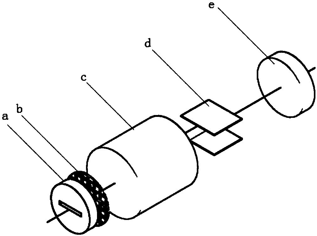
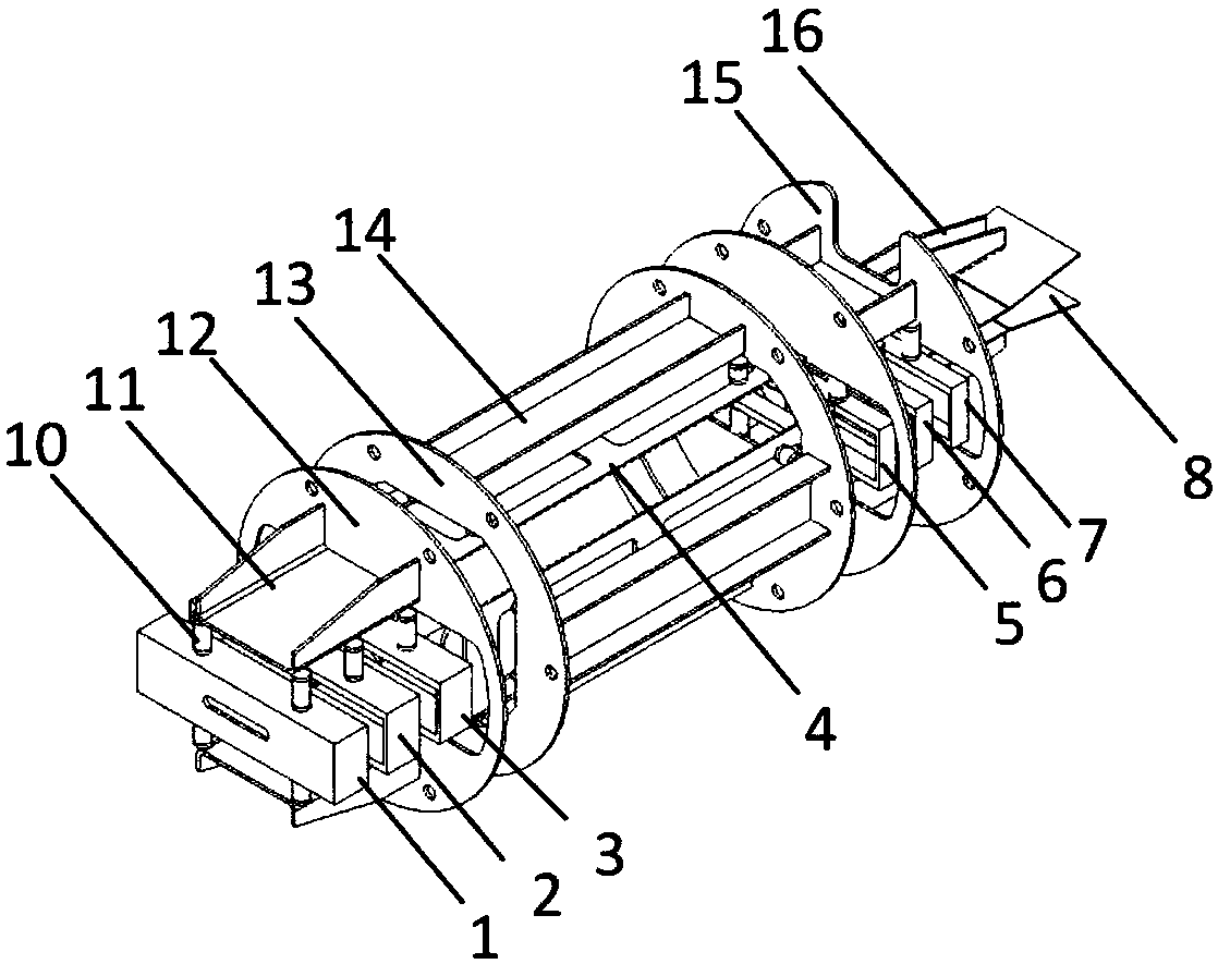
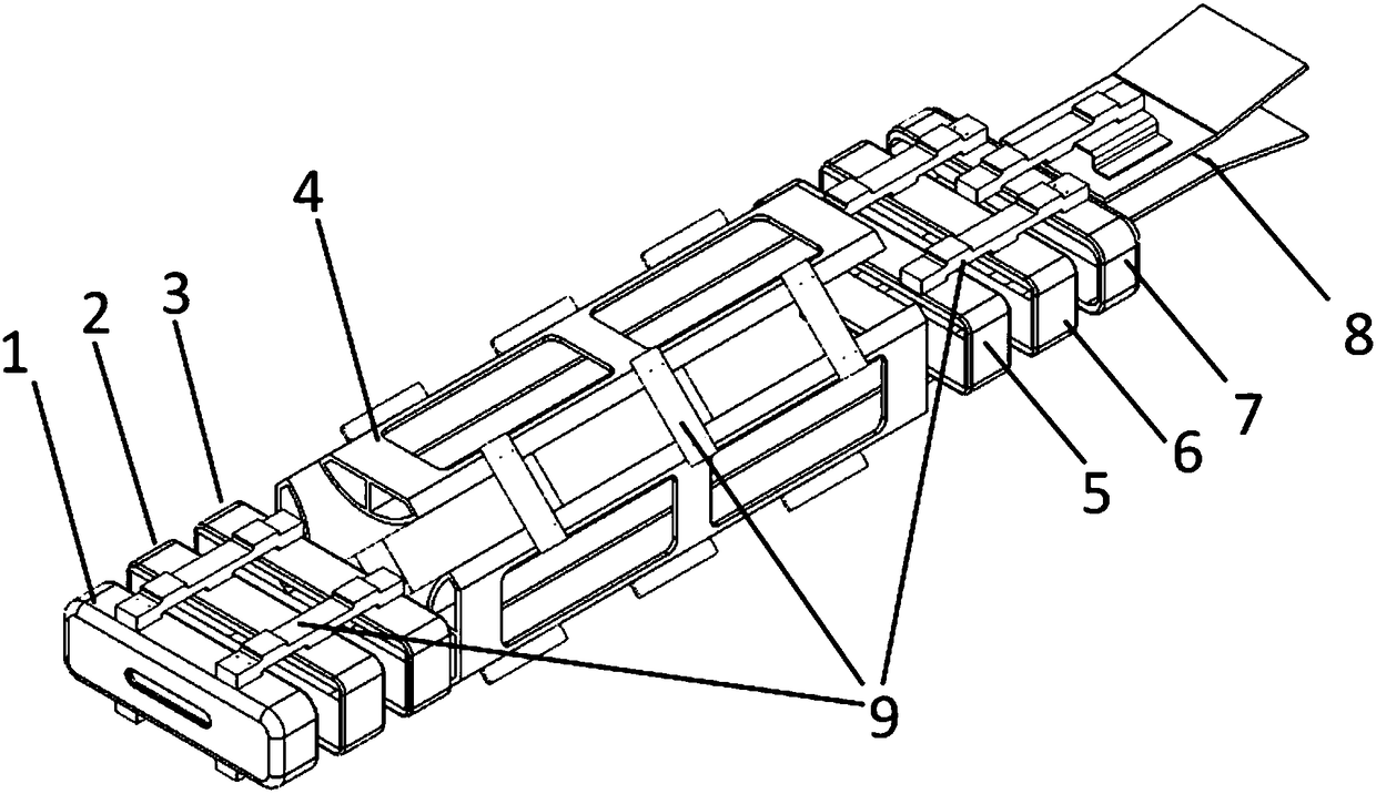
[0058] The time pre-focus electrode system and the time focus electrode system in the anisotropic focusing stripe image transformation tube are basically similar in structure, and the space electrode system is composed of four arc-surface electrodes with the same structure, which meet the conditions of group assembly. Therefore, In the assembly of the striped tube electro...


PUM


Abstract

The invention provides an assembling structure and method of an anisotropic high-dynamic streak image converter tube. By virtue of the assembling structure, the assembling precision of an electronic optical system of an anisotropic focusing streak image converter tube can be boosted, the assembling efficiency and percent of pass can be improved, and streak tube assembling consistency and interchangeability are enhanced, thereby improving the manufacturing efficiency and rate of finished products of the streak tube finally. The assembling structure is formed by three independent modules which are welded and fixed with a tube shell, wherein a time pre-focusing electrode module mainly consists of a G gate, an F1 focusing electrode and a B1 blanking electrode which are subjected to overall hot melting and sealing through multiple insulators; a space focusing electrode module mainly consists of four QL space electorates, and the four QL space electorates are adjacent in sequence in the circumferential direction, and are correspondingly subjected to overall hot melting and sealing through insulators; and a time focusing electrode and a deflecting plate joint module mainly consists of a B2 blanking electrode, an F2 focusing electrode, an A anode and two D deflecting plates which are subjected to overall hot melting and sealing through multiple insulators.

Description

Technical field: [0001] The invention relates to an assembly technology of an ultrafast diagnostic photoelectric device, in particular to an assembly structure and method of a stripe image transformation tube, a core component of a stripe camera. Background technique: [0002] Ultrafast phenomena (duration less than 1 μs) widely appear in natural or scientific and technological research. For example, the photosynthesis process of plants, the electrical pulse generated by VLSI, the carrier lifetime of semiconductor materials, the ultrafast photoexcited state relaxation process in laser materials, the molecular dynamics process of chemical reactions, the fluorescence emission of biological materials , The duration of the ultrashort laser pulse generated by the laser, the physical process of the interaction between strong light and matter, etc. are mostly in the range of picoseconds to femtoseconds, or even in the range of attoseconds [1] . Therefore, the study of ultrafast p...

Claims


Application Information

Patent Timeline
Patent Type & Authority Patents(China)
IPC IPC(8): H01J31/50H01J29/02H01J29/46H01J29/82
CPCH01J29/02H01J29/46H01J29/82H01J31/50
Inventor 卢裕田进寿赵卫王俊锋徐向晏赛小锋韦永林温文龙刘虎林辛丽伟
Owner XI'AN INST OF OPTICS & FINE MECHANICS - CHINESE ACAD OF SCI
Why Eureka
Try Eureka