
Efficient desilting device with good cleaning effect for hydraulic engineering

A water conservancy project and dredging device technology, which is applied to mechanically driven excavators/dredgers, earth movers/shovels, construction, etc., can solve problems such as poor crushing effect, pipeline blockage, and poor use effect, and achieve Improve crushing efficiency, facilitate repair and maintenance, and facilitate mud cleaning

Pending Publication Date: 2021-07-23
颖川建设工程有限公司
View PDF1 Cites 0 Cited by
  • Summary
  • Abstract
  • Description
  • Claims
  • Application Information

AI Technical Summary

Problems solved by technology

[0007] The purpose of the present invention is to provide a high-efficiency dredging device with good cleaning effect for water conservancy projects, which solves the problem that the sand and gravel particles in the mud will cause damage to the propeller blade and a large amount of soil sticks to the propeller blade due to long-term contact with the mud. It is inconvenient to clean the blade, it is inconvenient to disassemble the shell at the propeller blade, and it is inconvenient to repair and maintain the propeller blade regularly, which will lead to poor rotating crushing effect of the propeller blade and poor use effect; it is used for rotary crushing The propeller blades are fixed, and the broken blades have a poor crushing effect on sand and stone in the mud, which will easily cause large particles to block the pipeline when the dredge pump sucks mud, and the effect of mud suction and dredging is poor; mud suction The position of the mouth is fixed, it is inconvenient to adjust the mud suction angle, resulting in unsatisfactory mud suction effect and low working efficiency.

Method used


Image

  • Efficient desilting device with good cleaning effect for hydraulic engineering
  • Efficient desilting device with good cleaning effect for hydraulic engineering
  • Efficient desilting device with good cleaning effect for hydraulic engineering

Examples


Embodiment 1

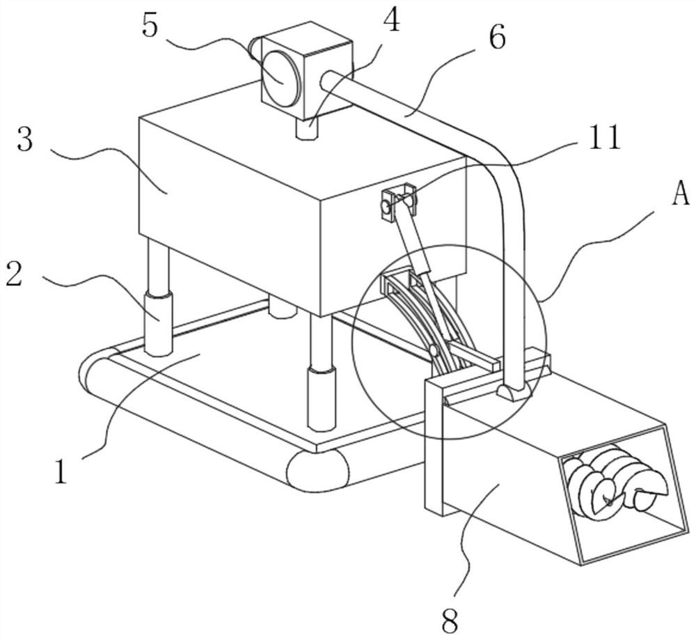
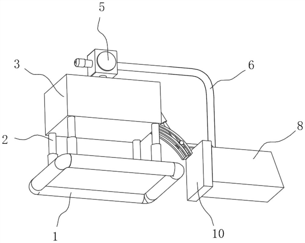
[0030] see Figure 1-7, the present invention provides a technical solution: a high-efficiency dredging device with good cleaning effect for water conservancy projects, comprising a floating plate 1, the four corners of the top of the floating plate 1 are fixedly connected with a hydraulic cylinder 2, and the top of the hydraulic cylinder 2 is fixedly connected with a The mud storage box 3, the top of the mud storage box 3 is fixedly connected with the mud inlet pipe 4, the top of the mud inlet pipe 4 is fixedly connected with the dredging pump 5, and one side of the mud pump 5 is fixedly connected with the connecting pipe 6, the connecting pipe 6 A mud scraper 8 is hinged at the bottom of the mud scraper 8, and a dismounting device 9 is provided on one side of the mud scraper 8. The dismounting device 9 includes a concave groove 901, and a convex block 902 is clamped on the inner wall of one side of the concave groove 901. The convex block The inside of 902 is connected with ...

Embodiment 2

[0033] see Figure 1-7 As shown, on the basis of Embodiment 1, the present invention provides a technical solution: the driving mechanism 10 includes a driving box 1001, the top inner wall of the driving box 1001 is fixedly connected with a hydraulic part 1002, and the bottom of the hydraulic part 1002 is fixedly connected with a gear plate 1003, one side of the gear plate 1003 is meshed with a gear one 1004, one side of the gear one 1004 is fixedly connected with a drive rod one 1005, one side of the drive rod one 1005 is rotatably connected with a movable seat one 1006, and the gear plate 1003 is far away from the gear one 1004 One side of gear two 1007 is meshed with gear two 1007, one side of gear two 1007 is fixedly connected with drive rod two 1008, one side of drive rod two 1008 is rotatably connected with movable seat two 1009, and the outer wall of drive rod one 1005 is fixedly connected with broken blades One 1010, the outer wall of the drive rod two 1008 is fixedly ...

Embodiment 3

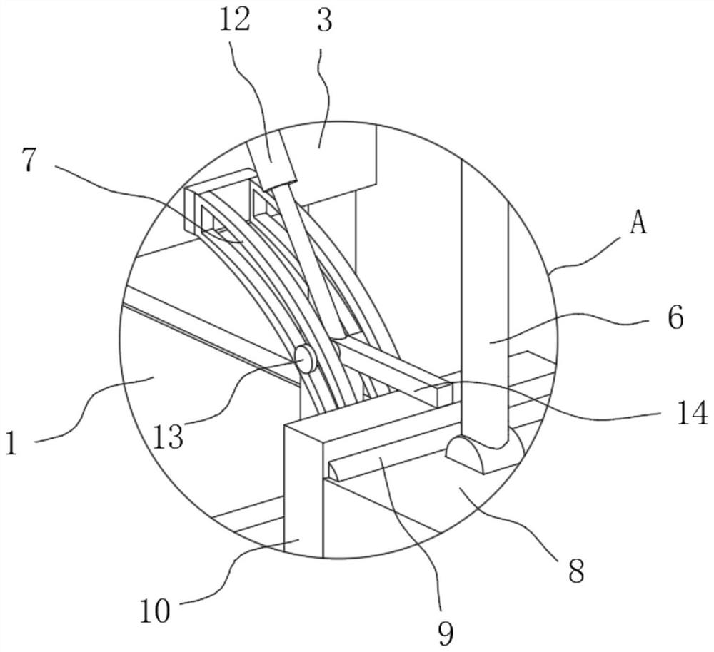
[0036] see Figure 1-7 As shown, on the basis of Embodiment 1 and Embodiment 2, the present invention provides a technical solution: one side of the outer wall of the mud storage box 3 is fixedly connected with an arc-shaped frame 7, and one side of the mud scraper 8 is passed through a disassembly device 9. A driving mechanism 10 is fixedly connected. One side of the outer wall of the mud storage box 3 is fixedly connected with a hinged support 11. One side of the hinged support 11 is hinged with a moving cylinder 12. The bottom of the moving cylinder 12 is fixedly connected with an H-shaped sliding column 13. One side of the H-shaped slid 13 is fixedly connected with a connecting rod 14, and one side of the arc-shaped frame 7 is provided with an arc-shaped hole that is compatible with the H-shaped slid 13, and the inner wall of the arc-shaped hole is connected with the H-shaped slid 13. The outer wall of the connecting rod 14 is fixedly connected to the top outer wall of the...


PUM


Abstract

The invention discloses an efficient desilting device with a good cleaning effect for hydraulic engineering, and relates to the technical field of desilting devices. The efficient desilting device comprises a floating plate, hydraulic cylinders are fixedly connected to the four corners of the top of the floating plate, and a mud storage box is fixedly connected to the tops of the hydraulic cylinders. Through an arranged dismounting device, a mud scraping bucket and a driving mechanism can be conveniently dismounted, when a rubber pressing block moves upwards and a threaded rod is rotated, a trapezoidal push block moves upwards, the thrust of the trapezoidal push block to hexagonal blocks at the two sides is released, the two hexagonal blocks get close to each other, and a limiting column slides along the inner wall of a limiting groove; and when a sliding rod rotates, a rotating rod rotates to be separated from the inner wall of a clamping groove, a convex block moves upwards to be separated from the inner wall of a concave groove, limitation of the mud scraping hopper facilitates splitting, disassembling is convenient to expose a first crushing paddle and a second crushing paddle, mud adhering to the surfaces of the first crushing paddle and the second crushing paddle is convenient to clean, repairing and maintaining are convenient, the rotating crushing effect of the crushing paddles is better, and sludge can be cleaned more conveniently.

Description

technical field [0001] The invention relates to the technical field of dredging devices, in particular to a high-efficiency dredging device for water conservancy projects with good cleaning effect. Background technique [0002] At present, river dredging generally refers to the treatment of rivers, which belongs to water conservancy projects. There are many rivers and lakes in our country, and the problem of sediment deposition is very serious. Desilting is an essential process. The dredging of water conservancy projects usually uses dredging machinery to blow and stir the silt deposited on the bottom of the river into turbid water, which flows away with the river water, thus playing a role in dredging. [0003] A kind of water conservancy engineering dredging device disclosed as Chinese patent CN211057900U, it is by setting arc-shaped dredging device below the hull, and the arc-shaped dredging side is equipped with an arc-shaped dredging mouth, and the arc-shaped dredging ...

Claims


Application Information

Patent Timeline
IPC IPC(8): E02F3/88E02F5/28
CPCE02F3/88E02F5/28
Inventor 张少华
Owner 颖川建设工程有限公司
Learn More