
Lake-near deep foundation pit dewatering device and construction method thereof

A technology for deep foundation pits and dewatering wells, applied in infrastructure engineering, construction, etc., can solve the problems of foundation pit bubbles, affecting vehicle driving, low safety and reliability, etc. groove, high safety and reliability effect

Active Publication Date: 2021-07-23
中国建筑土木建设有限公司
View PDF7 Cites 0 Cited by
  • Summary
  • Abstract
  • Description
  • Claims
  • Application Information

AI Technical Summary

Problems solved by technology

[0005] The invention provides a dewatering device for a deep foundation pit near a lake and its construction method, which is used to solve the problem that a submersible pump is usually used to connect hoses to the lowering and drainage of deep foundation pits near a lake at present, and the hose is laid around the foundation pit, which seriously affects the construction. Vehicles drive on site, and the safety and reliability are low, and water treatment accidents are prone to occur, resulting in technical problems that sometimes occur in foundation pits.

Method used


Image

  • Lake-near deep foundation pit dewatering device and construction method thereof
  • Lake-near deep foundation pit dewatering device and construction method thereof
  • Lake-near deep foundation pit dewatering device and construction method thereof

Examples


Embodiment Construction

[0039] The technical solutions of the present invention will be described in detail by the following examples. The following examples are only exemplary, and can only be used to explain and illustrate the technical solutions of the present invention, but cannot be construed as limitations on the technical solutions of the present invention.

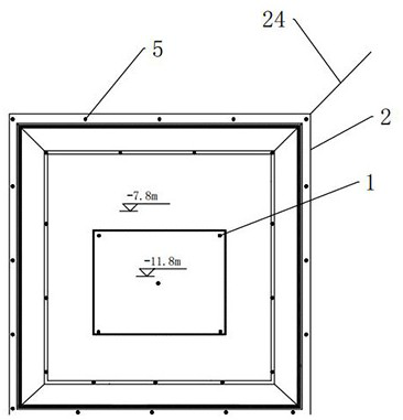
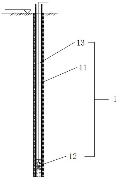
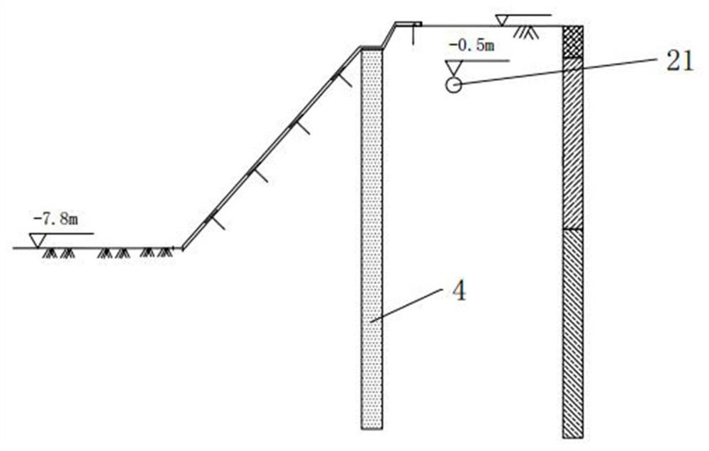
[0040] like figure 1 , a dewatering device for deep foundation pit near the lake, including a precipitation system 1, a drainage system 2, a collection system 3 and a secondary utilization system, such as figure 2 , the dewatering system 1 includes a number of dewatering wells 11, a submersible pump 12 respectively arranged at the bottom of the dewatering well 11, and a drainage hose 13 connected to the submersible pump 12, such as Figure 4 and Figure 5 , the drainage system 2 includes a communication row pipe 21 buried under the surface, the communication row pipe 21 is provided with a number of vertical pipes 22 extending out of the...


PUM


Abstract

The invention discloses a lake-near deep foundation pit dewatering device. The lake-near deep foundation pit dewatering device comprises a dewatering system, a drainage system, a collection system and a secondary utilization system; the dewatering system comprises a plurality of dewatering wells, a submersible pump and drainage hoses; the drainage system comprises a buried communication calandria, vertical pipes are arranged on the communication calandria, a plurality of fixers are arranged on the vertical pipes, the multiple drainage hoses respectively communicate with the top ends of the vertical pipes through the fixers, and the communication calandria communicates with a drainage pipe; the collection system comprises a glass fiber reinforced plastic water tank, a water inlet pipe and a water outlet pipe; the secondary utilization system comprises a filtering and purifying device and a pressurizing device. A groove is excavated beside a foundation pit, the communication calandria is embedded in the groove, the multiple vertical pipes are arranged on the communication calandria, and the drainage hoses in the dewatering wells are correspondingly connected to the vertical pipes beside, so that on one hand, dewatering can be reutilized, on the other hand, only the spaced vertical pipes are arranged on the ground surface, on-site construction vehicles can run among the vertical pipes, and the problem that running of the on-site construction vehicles is affected due to the fact that the drainage hoses directly communicate into a lake is solved.

Description

technical field [0001] The invention belongs to the field of foundation pit dewatering construction, in particular to a dewatering device for a deep foundation pit near a lake and a construction method thereof. Background technique [0002] Foundation pit dewatering means that when the foundation pit is excavated, the groundwater level is higher than the excavation bottom surface, and the groundwater will continue to seep into the pit. Pit bottom piping and precipitation work due to the decrease of the bearing capacity of the foundation. [0003] With the increase of economic development and social demand in my country, the number of deep foundation pit projects near the lake has gradually increased. Such deep foundation pit projects are closely related to the lake hydraulics, the groundwater is extremely rich, and the seepage field is very complex. It is very difficult to come, which seriously restricts the smooth progress of the project. [0004] At this stage, water-stop...

Claims


Application Information

Patent Timeline
IPC IPC(8): E02D19/10
CPCE02D19/10
Inventor 赵韦皓郭志光张凡吕柏行王子进陈振邦
Owner 中国建筑土木建设有限公司
Learn More