
A buffer device for adjusting the angle of the shunt door of the coal drop pipe of a stacker and reclaimer

A technology of angle adjustment and buffer device, which is applied in the direction of conveyor control device, conveyor, loading/unloading, etc., can solve problems such as imbalance, overload shutdown of downstream belt conveyor, etc., to improve accuracy rate, avoid overload shutdown, and high reliability Effect

Active Publication Date: 2022-07-08
HUANENG SHANGHAI SHIDONGKOU SECOND POWER PLANT
View PDF12 Cites 0 Cited by
  • Summary
  • Abstract
  • Description
  • Claims
  • Application Information

AI Technical Summary

Problems solved by technology

As a result, there is a hidden danger that the proportion of coal blending and combustion will be out of balance for a period of time and the risk of excessive flow adjustment will cause the downstream belt conveyor to overload and stop.

Method used


Image

  • A buffer device for adjusting the angle of the shunt door of the coal drop pipe of a stacker and reclaimer
  • A buffer device for adjusting the angle of the shunt door of the coal drop pipe of a stacker and reclaimer
  • A buffer device for adjusting the angle of the shunt door of the coal drop pipe of a stacker and reclaimer

Examples


Embodiment 1

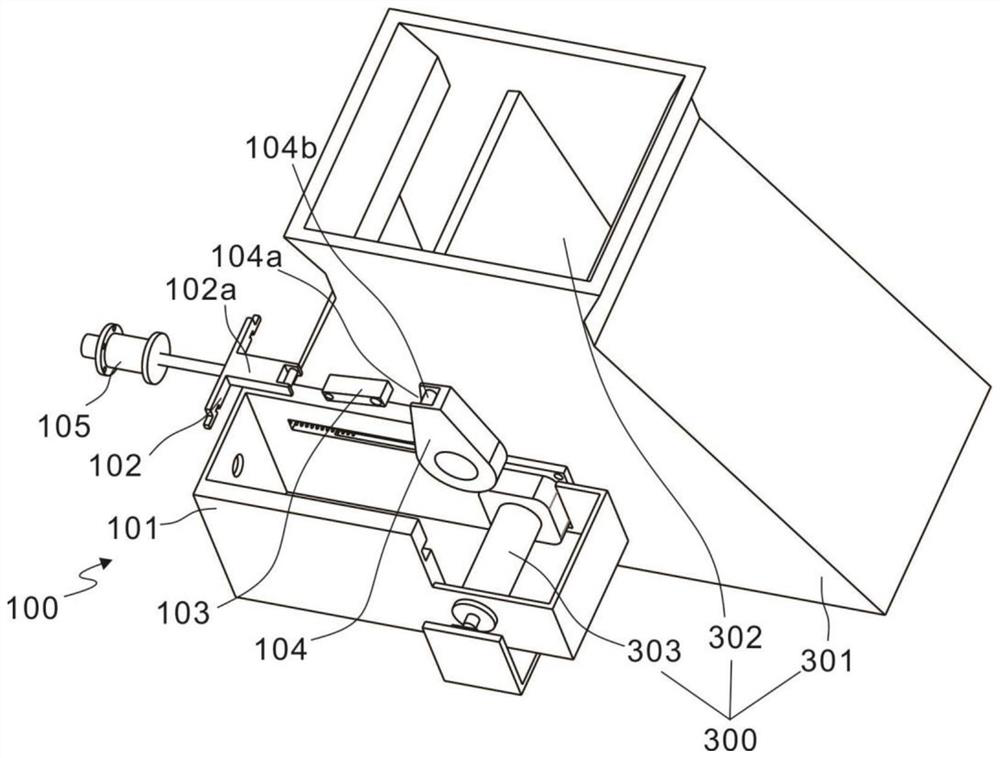
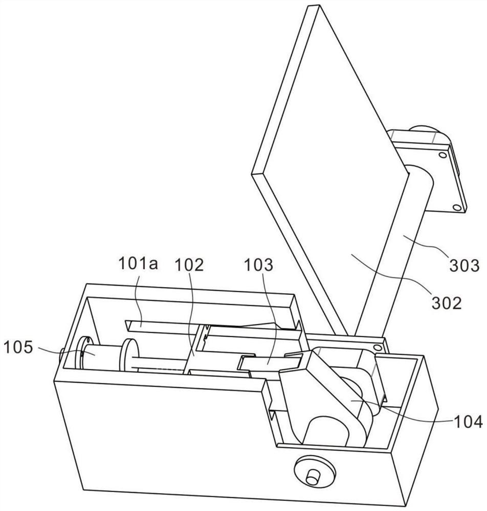
[0036] refer to Figures 1 to 3 , which is the first embodiment of the present invention. This embodiment provides a stacker-reclaimer coal drop pipe diverter door angle adjustment buffer device, which includes an angle adjustment assembly 100 and a coal drop assembly 300, and the angle adjustment assembly 100 is arranged in the drop The outer wall of the coal assembly 300 is used to control the mixing ratio of two kinds of coals in the falling coal assembly 300 .

[0037] The coal drop assembly 300 includes a coal drop pipe 301, a diverter door 302 and a rotating shaft 303. The coal drop tube 301 is an existing device, and the diverter door 302 is a square plate-like structure, which is arranged inside the coal drop tube 301, and the rotating shaft 303 transversely passes through it. The coal falling pipe 301 is erected on the outer walls of both sides of the coal falling pipe 301, and then one end of the shunt door 302 is fixed on the rotating shaft 303. The rotation of the ...

Embodiment 2

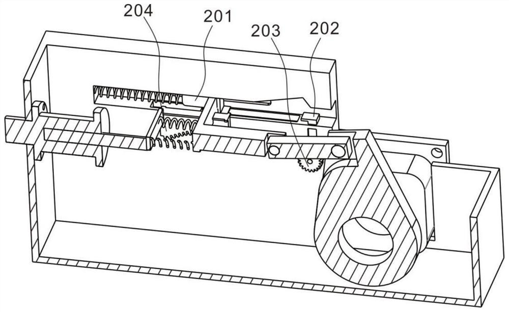
[0044] refer to Figures 4 to 10 , is the second embodiment of the present invention, which is based on the previous embodiment, and further includes a buffer assembly 200 , which is arranged on both sides of the interior of the installation shell 101 and is movably connected with the angle adjustment assembly 100 .

[0045] The buffer assembly 200 includes a pulling member 201, a floating block 202 and a gear 203. Specifically, the pulling member 201 includes a first elastic member 201a and a clamping block 201b. The bottom of the first sliding groove 101a is provided with a second sliding groove 101b, and the clamping block 201b The bottom is provided with a second elastic piece 201b-2, the other end of the second elastic piece 201b-2 is fixedly provided with an insert 201b-3, the second elastic piece 201b-2 is in a compressed state in a normal state, and the insert 201b-3 is embedded in the second elastic piece 201b-3. The second chute 101b can be used to stabilize the move...


PUM


Abstract

The invention discloses an angle adjustment buffer device for a shunt door of a coal drop pipe of a stacker and reclaimer, which comprises an angle adjustment assembly, and the angle adjustment assembly includes a mounting shell, a push plate, a hinge plate and a rotating block. The inner wall of the installation shell is slidably connected, one end of the hinge plate is hinged with the push plate, and the other end is hinged with the rotating block; The pulling pieces are arranged on both sides of the inner wall of the installation shell and are connected with the push plate, the floating block is arranged in the inner walls of both sides of the installation shell, and the gear is installed on the floating block; the present invention responds It has fast time, strong adaptability to the environment, high reliability, and has a certain buffer distance, which avoids the damage of the shunt door caused by the error of the push rod motor.

Description

technical field [0001] The invention relates to the technical field of angle adjustment of the shunt door of a coal drop pipe, in particular to a buffer device for adjusting the angle of the shunt door of a coal drop pipe of a stacker and reclaimer. Background technique [0002] Today, under the dual pressure of environmental protection and high coal prices, and on the premise of ensuring that the environmental protection indicators meet the standards, power plants often use good coal and poor coal to mix and burn in order to reduce the cost of power generation. When the coal enters the raw coal bunker from the dock through the coal drop pipe of the stacker and reclaimer, if the two types of coal are mixed and burned, the driver can change the coal flow in the coal drop pipe by adjusting the position of the diverter door. Although the coal flow can be known through the belt scale on the downstream belt conveyor, one of the feedback time is too long, and the other is to be co...

Claims


Application Information

Patent Timeline
Patent Type & Authority Patents(China)
IPC IPC(8): B65G11/02B65G11/20B65G65/32B65G65/28B65G43/08
CPCB65G11/026B65G11/206B65G65/32B65G65/28B65G43/08B65G2201/045B65G2203/042
Inventor 顾孟贤史聪陈业勤江乐兴
Owner HUANENG SHANGHAI SHIDONGKOU SECOND POWER PLANT
Learn More