Structure for air safety operation and construction method thereof
A technology for safe operation and construction method, which is applied in the direction of housing structure support, housing structure support, scaffolding supported by housing structure, etc., can solve the problem of unguaranteed quality, and achieve the effect of simple construction and safe operation space.
- Summary
- Abstract
- Description
- Claims
- Application Information
AI Technical Summary
Problems solved by technology
Method used
Image

Examples
Embodiment 1
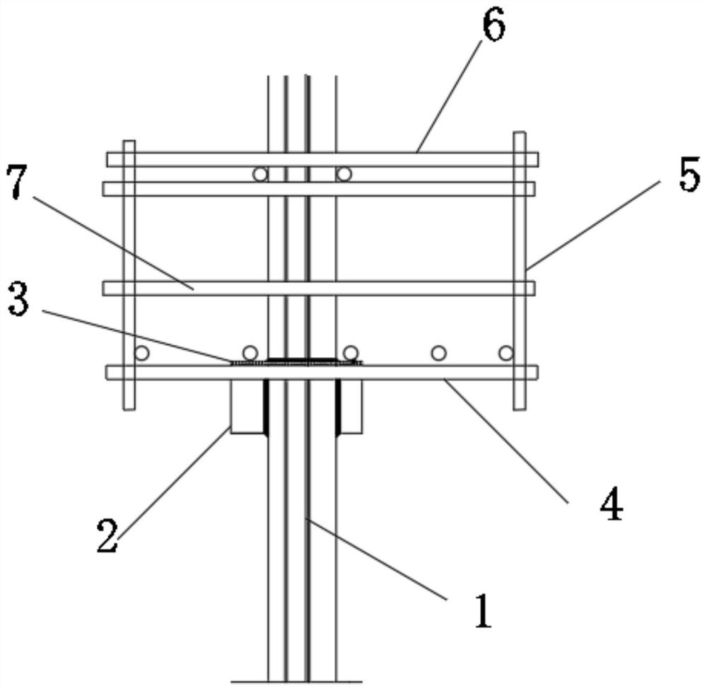
[0019] like figure 1 As shown, in this embodiment, a structure for safe work in the air includes a steel column 1, a load-bearing structure 2 arranged on the steel column 1, a limit plate 3 detachably connected to the load-bearing structure 2, and a load-bearing structure 3 arranged on the load-bearing The working platform 4 between the structure 2 and the limit disk 3.
[0020] In this embodiment, the load-bearing structure 2 can be prefabricated on the steel column 1, and the cross-sectional area of the load-bearing structure 2 is smaller than the cross-sectional area of the steel column 1, so that the load-bearing structure 2 will not affect the construction of the steel column 1, or Interfere with other structures and affect the construction of other structures. The bearing structure 2 is used as the installation and positioning basis to provide space for the positioning and installation of the working platform 4, and the working platform 4 is clamped by the connectio...
Embodiment 2
[0022] On the basis of the above embodiments, in this embodiment, the load-bearing structure 2 adopts a steel rectangular tube, so that the load-bearing structure 2 has the advantages of convenient welding, high strength, high rigidity, and strong bearing capacity.
[0023] In this embodiment, there are four load-bearing structures 2 that are evenly distributed around the steel column 1 . In this way, the supported effective area of the working platform 4 can be increased, and the pressure from the working platform 4 can be shared by multiple load-bearing structures 2 , which can reduce the pressure on a single load-bearing structure 2 , thereby improving safety. Moreover, the working platform 4 can be supported from multiple positions, and the balance of the working platform 4 can be improved.
Embodiment 3
[0025] On the basis of the above embodiments, in this embodiment, there are two working platforms 4, which are symmetrically distributed on both sides of the steel column 1 . In this way, when the working platform 4 is installed, the two working platforms 4 can be hoisted to corresponding positions and then assembled, so that the working platform 4 can avoid other structures during the hoisting process.
[0026] The two working platforms 4 can be detachably connected, so that the stability of the working platforms 4 can be improved. For example, screw connections can be used.
[0027] In this embodiment, several railings 5 are provided on the upper surface of the working platform 4 . Utilizing the railing 5 can form an enclosure structure on the working platform 4 , improve safety performance, and prevent workers from falling from around the working platform 4 .
[0028] In this embodiment, a connecting rod 7 is detachably connected between the railings 5 on the two work...
PUM
 Abstract
Description
Claims
Application Information
 - R&D
- Intellectual Property
- Life Sciences
- Materials
- Tech Scout
- Unparalleled Data Quality
- Higher Quality Content
- 60% Fewer Hallucinations
Browse by: Latest US Patents, China's latest patents, Technical Efficacy Thesaurus, Application Domain, Technology Topic, Popular Technical Reports.
© 2025 PatSnap. All rights reserved.Legal|Privacy policy|Modern Slavery Act Transparency Statement|Sitemap|About US| Contact US: help@patsnap.com