Optical imaging lens
An optical imaging lens and lens technology, applied in optics, optical components, instruments, etc., can solve the problems of poor imaging quality of telephoto lenses, achieve the effect of small chromatic aberration, increase imaging quality, and ensure imaging quality
- Summary
- Abstract
- Description
- Claims
- Application Information
AI Technical Summary
Problems solved by technology
Method used
Image

Examples
Embodiment 1
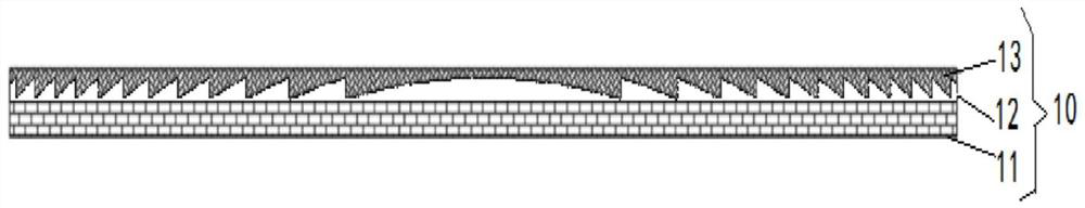
[0067] Such as Figure 1 to Figure 16 As shown, along the optical axis from the object side of the optical imaging lens to the image side of the optical imaging lens, it includes a first lens, a second lens, a third lens, a prism and a diffraction element 10, the first lens has a positive refractive power; the second lens It has negative refractive power; the third lens has positive refractive power; the diffraction element 10 is arranged between the prism and the object to be shot, and the diffraction efficiency ef of the diffraction element 10 in the range of visible light is ≥ 80%.
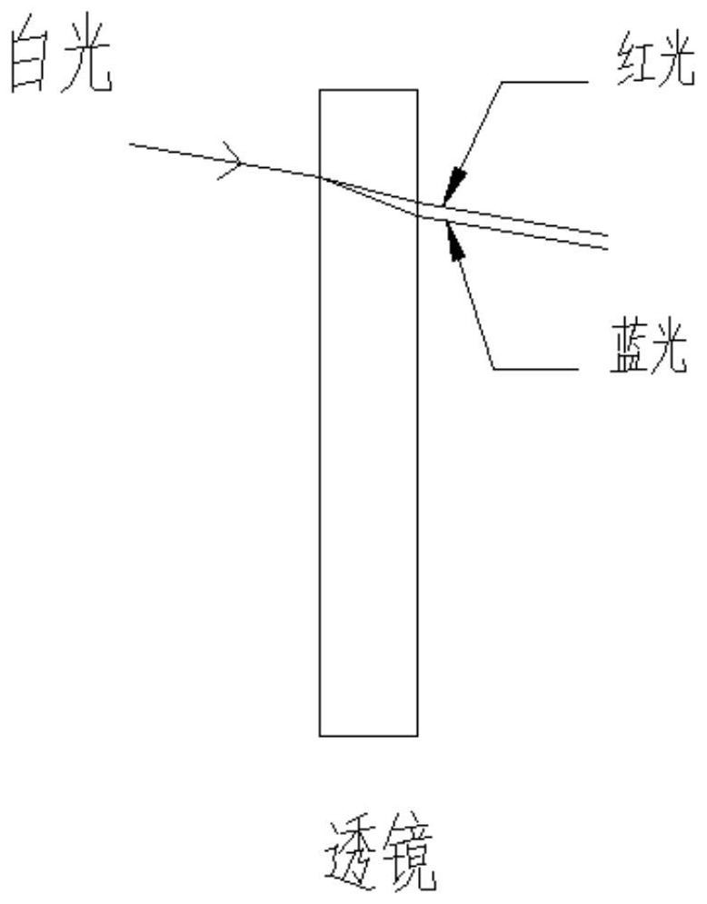
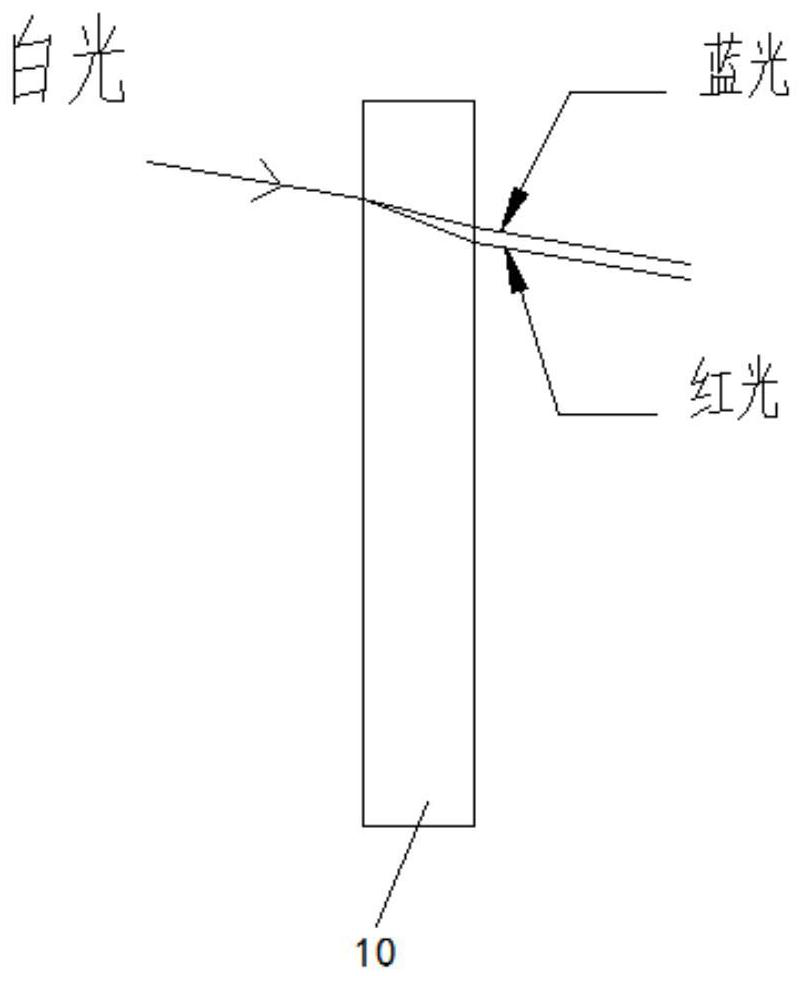
[0068] By arranging the prism on the optical imaging lens, the chromatic aberration of the optical imaging lens can be balanced, and the imaging quality of the optical imaging lens can be effectively increased. The diffractive element 10 has a unique negative dispersion characteristic, which can correct the chromatic aberration of the optical system when combined with the optical system, so tha...
Embodiment 2
[0090] Such as Figure 1 to Figure 16 As shown, along the optical axis from the object side of the optical imaging lens to the image side of the optical imaging lens, it includes a first lens, a second lens, a third lens, a prism and a diffraction element 10, the first lens has a positive refractive power; the second lens It has negative refractive power; the third lens has positive refractive power; the diffractive element 10 is arranged between the prism and the object to be shot, and the thickness T4 of the diffractive element 10 satisfies: T4<0.6mm.
[0091]By arranging the prism on the optical imaging lens, the chromatic aberration of the optical imaging lens can be balanced, and the imaging quality of the optical imaging lens can be effectively increased. The diffractive element 10 has a unique negative dispersion characteristic, which can correct the chromatic aberration of the optical system when combined with the optical system, so that the optical imaging lens has le...
PUM
| Property | Measurement | Unit |
|---|---|---|
| refractive index | aaaaa | aaaaa |
| Abbe number | aaaaa | aaaaa |
| angle | aaaaa | aaaaa |
Abstract
Description
Claims
Application Information
 - R&D
- Intellectual Property
- Life Sciences
- Materials
- Tech Scout
- Unparalleled Data Quality
- Higher Quality Content
- 60% Fewer Hallucinations
Browse by: Latest US Patents, China's latest patents, Technical Efficacy Thesaurus, Application Domain, Technology Topic, Popular Technical Reports.
© 2025 PatSnap. All rights reserved.Legal|Privacy policy|Modern Slavery Act Transparency Statement|Sitemap|About US| Contact US: help@patsnap.com