Optical system and projection device

An optical system and light technology, applied in the field of projection, can solve the problems of limited display unit display resolution of the projection device and the inability to increase the resolution of the projected image, etc., and achieve the effect of increasing the resolution

Active Publication Date: 2022-01-14
GOERTEK OPTICAL TECH CO LTD
View PDF0 Cites 0 Cited by
  • Summary
  • Abstract
  • Description
  • Claims
  • Application Information

AI Technical Summary

Problems solved by technology

[0003] The present invention provides an optical system and a projection device, aiming to solve the problem in the prior art that the projection device is limited by the display resolution of the display unit, and the resolution of the projected image cannot be increased

Method used


Image

  • Optical system and projection device
  • Optical system and projection device
  • Optical system and projection device

Examples


no. 1 example

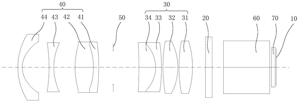
[0085] In the first embodiment, the design data of the optical system is as shown in Table 1:

[0086] Table 1

[0087]

[0088] Wherein, the focal length f of the optical system is 9mm;

[0089] The aperture number Fno of the optical system is 1.7;

[0090] The overall length of the optical system is 78mm.

[0091] Wherein, the light incident surface and the light exit surface of the first lens 31 and the light incident surface and the light exit surface of the eighth lens 44 are aspheric structures, wherein A4, A6, A8, and A10 are aspheric high-order aspheric lenses. Item coefficients, as shown in Table 2.

[0092] Table 2

[0093]

[0094]

[0095] Wherein, the light incident surface and the light exit surface of the first lens 31 and the light incident surface and the light exit surface of the eighth lens 44 are even-order aspheric surfaces, wherein the even-order aspheric surfaces satisfy the following relationship:

[0096]

[0097] Among them, Y is the ...


PUM


Abstract

The invention discloses an optical system and a projection device. The optical system sequentially includes a display unit, a vibrating mirror, a first mirror group and a second mirror group along the light transmission direction; Light transmission direction; the first lens group has positive refractive power; the second lens group has positive refractive power. The optical system satisfies the following relationship: 17.5

Description

technical field [0001] The invention relates to the field of projection technology, in particular to an optical system and a projection device. Background technique [0002] Micro projection is a projection technology that miniaturizes and makes portable the traditional projection device. In the field of micro-projection technology, micro-projection equipment is gradually developing in the direction of miniaturization, high brightness, and portability. In the current micro-projection equipment, because the display unit is fixed, the display resolution of the micro-projection equipment cannot be increased. When a high-resolution image is displayed through the micro-projection device, it is limited by the resolution of the display unit, thereby affecting the picture quality of the projected image. Contents of the invention [0003] The present invention provides an optical system and a projection device, aiming at solving the problem in the prior art that the projection dev...

Claims


Application Information

Patent Timeline
Patent Type & Authority Patents(China)
IPC IPC(8): G03B21/00G03B21/14
CPCG03B21/008G03B21/142
Inventor 丁卫涛龚敬剑
Owner GOERTEK OPTICAL TECH CO LTD
Why Eureka
Try Eureka