Zoom lens with forward-located aperture stop

a technology of aperture stop and zoom lens, which is applied in the field of zoom lenses, can solve the problems of weight, cost, and the inability to make the first positive lens group large in diameter, and achieve the effects of low breathing, high relative illumination, and increased efficiency of many electronic sensors

Active Publication Date: 2016-02-02
NEIL IAIN A
View PDF21 Cites 0 Cited by
  • Summary
  • Abstract
  • Description
  • Claims
  • Application Information

AI Technical Summary

Benefits of technology

[0008]The negatively powered front (first) lens group may provide focusing by movement of at least one of the lens elements contained therein, and may exhibit low breathing in at least a portion of the zoom range. The fourth lens group is adjacent the image space and is used to match the optical characteristics of the zoom lens to an image sensor and in particular to deliver the radiation passing through the zoom lens and on to the image sensor with nearly telecentric light paths and suitably high relative illumination, thereby increasing the efficiency of many electronic sensors. The fourth lens group may have positive optical power.

Problems solved by technology

This arrangement of negative and positive optical powers in the zooming portion has a possible disadvantage of making the first positive lens group large in diameter, weight and cost especially where wide fields of view and focusing is required and in particular where focus breathing is controlled during focusing.

Method used


Image

  • Zoom lens with forward-located aperture stop
  • Zoom lens with forward-located aperture stop
  • Zoom lens with forward-located aperture stop

Examples


embodiments 1-3

Specifications for Embodiments 1-3

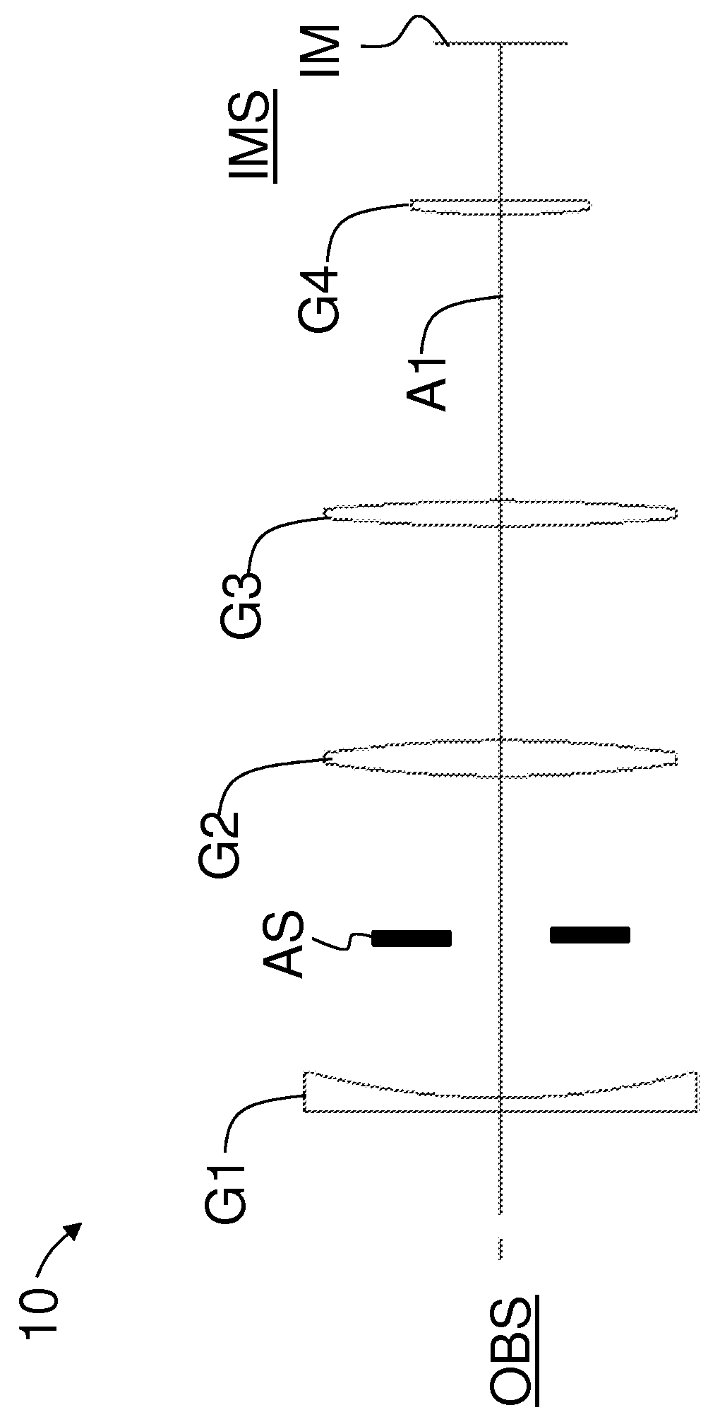
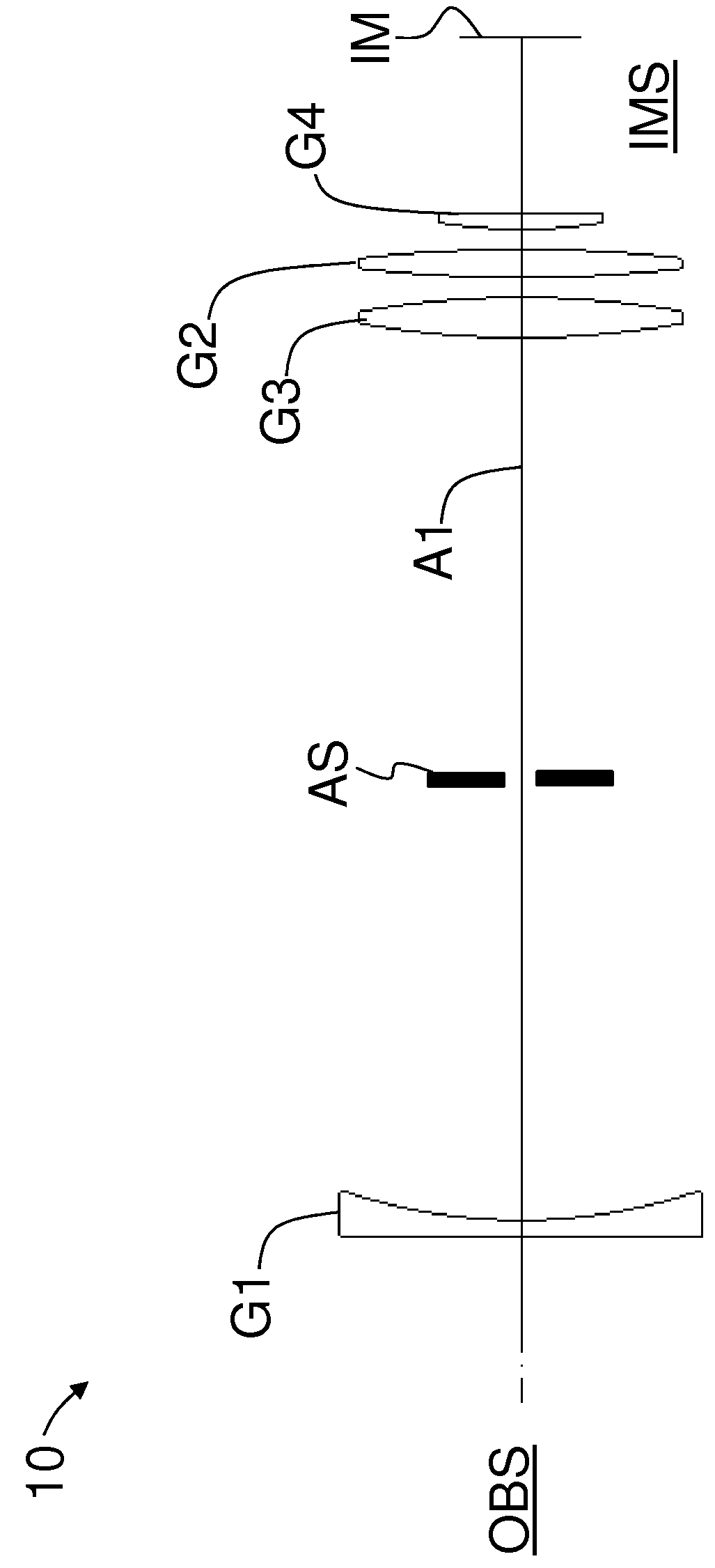
[0095]The three example embodiments of zoom lens 10 disclosed herein are meant to represent three of the most common types of zoom lenses used in cinematography. The first is a small, compact, small zoom ratio, a fairly fast aperture (f / no.) lens primarily for light weight applications, such as hand-held operation of the camera system. The second is a medium size, medium zoom ratio, moderate aperture lens which would be a “workhorse” lens since it is suitable for many applications and shooting situations. The third is a larger, i.e. longer, but compact in diameter, larger zoom ratio, moderate aperture lens, which would be more suitable for use when supported on a tripod, dolly, crane, etc.

[0096]Zoom lens 10 can be configured to have substantially constant full aperture throughout the zooming and focus ranges, and good close-focusing capabilities. The example focal lengths used in the embodiments described below are based on the actual field of view ...

embodiment 1

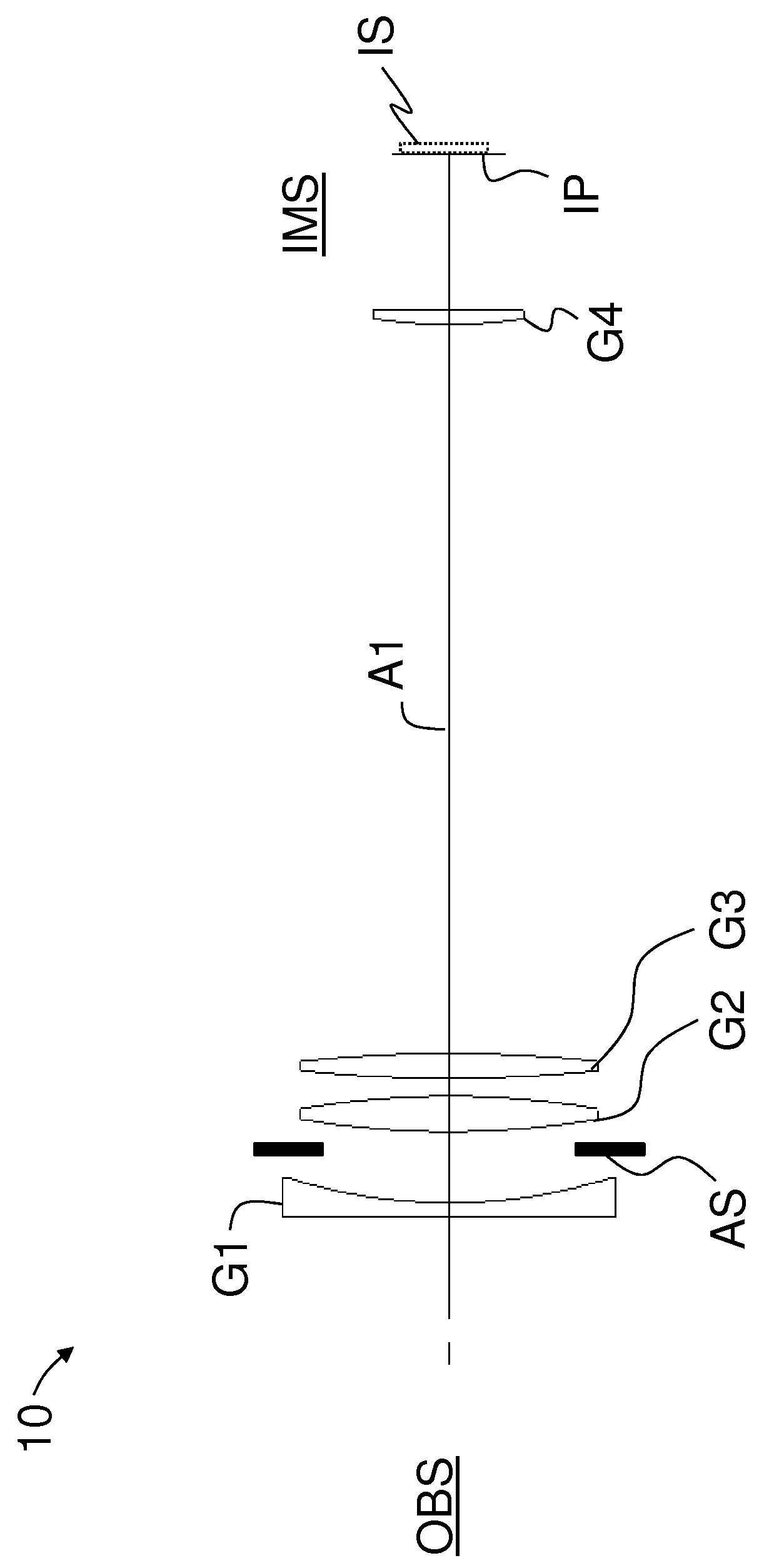
[0097]FIG. 2 is a lens diagram of a first main example embodiment (“embodiment 1”) of zoom lens 10. FIG. 2 includes annotation for lenses 1 through 22 and surfaces S1 through S45 to match the Optical Prescription Tables set forth below. The focal length is 28.36 mm at a far focus distance. Axial movement is indicated in FIG. 2 by the straight single-ended and double-ended arrows.

[0098]First lens group G1 includes from objectwise to imagewise first lens sub-group G1a, a second lens sub-group G1b and a third lens sub-group G1c. First lens sub-group G1a includes lens elements 1 and 2. Second lens sub-group G1b includes lens elements 3, 4 and 5, and is shown as being axially movable for focusing. Third lens sub-group G1c includes lens elements 6 and 7. Second lens group G2 includes lens elements 8 through 15. Third lens group G3 includes lens elements 16 through 19. Fourth lens group G4 includes lens elements 20 through 22. Object plane OB is the same as surface S1 and image plane IM is...


PUM


Abstract

A zoom lens including, along an optical axis and in order from an object space to an image space: first lens group with negative power; an aperture stop; a second lens group with positive power; a third lens group with positive power; and a fourth lens group. The second and third lens groups and the aperture stop are axially movable for zooming. At least one lens element in the first lens group is moveable to provide for focusing. The aperture stop moves independently of the lens groups during zooming and has a clear aperture that changes size during zooming.

Description

CLAIM OF PRIORITY[0001]This application claims the benefit of priority under 35 U.S.C. §119(e) of U.S. Provisional Application Ser. No. 61 / 615,286, filed on Mar. 25, 2012, and which is incorporated by reference herein.FIELD[0002]The disclosure relates to zoom lenses, and in particular to a family of zoom lenses having relatively compact front diameter optics and corresponding potential minimized weight and cost by having a forward-located aperture stop.BACKGROUND ART[0003]Contemporary zoom lens power configurations normally have an optical axis and are commonly based on a negative (−) and positive (+) combination of lens groups to provide zooming which are usually, but not always, preceded by a positive (+) lens group which provides focusing and following those lens groups a positive (+) lens group is employed to converge the radiation to a sensor in image space.[0004]This arrangement of negative and positive optical powers in the zooming portion has a possible disadvantage of makin...

Claims


Application Information

Patent Timeline
Patent Type & Authority Patents(United States)
IPC IPC(8): G02B15/14G02B15/177G02B15/167H04N5/225
CPCG02B15/14G02B15/167G02B15/177H04N5/2254G02B15/144515H04N23/55
Inventor NEIL, IAIN, A.
Owner NEIL IAIN A
Why Eureka
Try Eureka