
Five-degree-of-freedom probe clamping device for pneumatic probe calibration

A clamping device and a degree of freedom technology, applied in the field of wind tunnel testing, which can solve the problems of deviation from the center of the nozzle outlet, low calibration efficiency, and no automatic adjustment function of the calibration position.

Active Publication Date: 2021-07-16
中国空气动力研究与发展中心空天技术研究所
View PDF5 Cites 7 Cited by
  • Summary
  • Abstract
  • Description
  • Claims
  • Application Information

AI Technical Summary

Problems solved by technology

[0003] Most of the probe clamping devices currently in use only have the ability to automatically adjust the attitude of pitch and yaw two degrees of freedom. For probes with different pole lengths and heights, it is necessary to adjust the depth and height The direction of the calibration position is adjusted so that the sensing part of the probe is placed in the center of the nozzle outlet. Since the probe holding device only has the ability to adjust the attitude of the pitch and yaw two degrees of freedom, the whole or the probe holding device has to be adjusted. Part of the position adjustment is achieved by changing the bolt fixing position, the operation process is very cumbersome and inconvenient
[0004] At the same time, since there is no automatic adjustment function of the calibration position in the depth direction (Z direction), when calibrating a probe with multiple sensing parts arranged in a comb shape, it is necessary to calibrate one sensing part of the probe. Stop blowing, open the calibration wind tunnel test chamber, manually adjust the probe clamping device, place the second sensing part at the center of the nozzle outlet, and then start the calibration wind tunnel to calibrate the second sensing part until all sensing parts are completed. The calibration of the sensing part, the calibration efficiency is low
Moreover, for a longer probe with multiple sensing parts arranged in a comb shape, it is impossible for each sensing part to be on the pitch axis or yaw axis at the same time, which will cause each sensing part to deviate from the center of the nozzle outlet, resulting in to calibrate the error

Method used


Image

  • Five-degree-of-freedom probe clamping device for pneumatic probe calibration
  • Five-degree-of-freedom probe clamping device for pneumatic probe calibration
  • Five-degree-of-freedom probe clamping device for pneumatic probe calibration

Examples


Embodiment 1

[0038] The method of using the five-degree-of-freedom probe clamping device for pneumatic probe calibration in this embodiment is as follows:

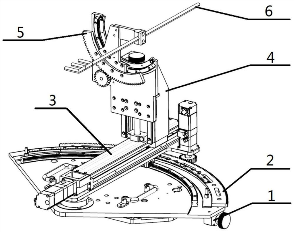
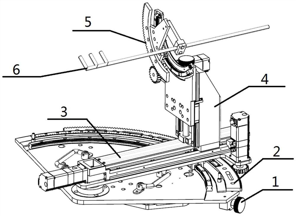
[0039] Before calibrating the probe 6, first replace the clamping part 51 adapted to the probe 6, and clamp the probe 6 stably on the clamping part 51; secondly, adjust the pitch mechanism 5 and the yaw mechanism 2 to the zero position, Then adjust the X-direction displacement mechanism 1, Y-direction displacement mechanism 4 and Z-direction displacement mechanism 3 in turn to ensure that the first sensing part of the probe 6 is located in the core flow field of the nozzle outlet; then set the pitch of each calibration state Angle, yaw angle, and Z-coordinates of other sensing parts; finally, the calibration wind tunnel is opened, and each sensing part is calibrated with variable pitch angle and yaw angle in turn.


PUM


Abstract

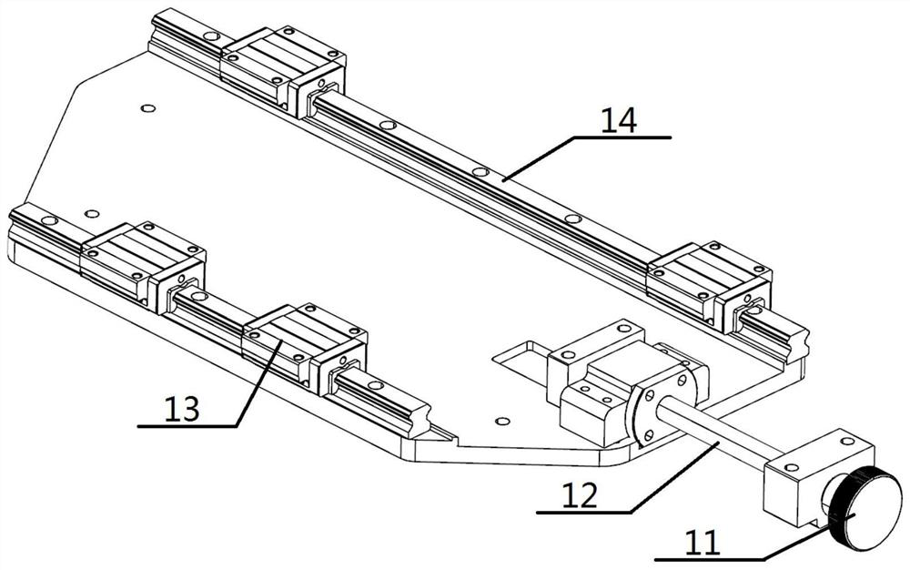
The invention discloses a five-degree-of-freedom probe clamping device for pneumatic probe calibration. The five-degree-of-freedom probe clamping device comprises an X-direction displacement mechanism, a yaw mechanism, a Z-direction displacement mechanism, a Y-direction displacement mechanism and a pitching mechanism, wherein the yaw mechanism is fixed on the X-direction displacement mechanism and realizes yaw through matching of an arc rack and a gear which are positioned on a horizontal plane; the Z-direction displacement mechanism is fixed on the radius of the arc rack of the yaw mechanism; the Y-direction displacement mechanism is fixed on the Z-direction displacement mechanism and is perpendicular to the Z-direction displacement mechanism; the pitching mechanism is fixed to the Y-direction displacement mechanism and achieves pitching through cooperation of an arc rack and a gear which are located on the vertical plane; the pitching mechanism is provided with a clamping component; the probe is fixed on the clamping component. The X-direction displacement mechanism, the yaw mechanism, the Z-direction displacement mechanism, the Y-direction displacement mechanism and the pitching mechanism are respectively adjusted or adjusted in a combined mode to change the calibration position of the probe. The five-degree-of-freedom probe clamping device is complete in function, convenient to operate and capable of achieving firm clamping and five-degree-of-freedom movement of the probe.

Description

technical field [0001] The invention belongs to the technical field of wind tunnel tests, and in particular relates to a five-degree-of-freedom probe clamping device for calibrating pneumatic probes. Background technique [0002] During the calibration process of the pneumatic probe, a probe clamping device is usually used to clamp the calibrated probe and adjust the calibration position and attitude. [0003] Most of the probe clamping devices currently in use only have the ability to automatically adjust the attitude of pitch and yaw two degrees of freedom. For probes with different pole lengths and heights, it is necessary to adjust the depth and height The direction of the calibration position is adjusted so that the sensing part of the probe is placed in the center of the nozzle outlet. Since the probe holding device only has the ability to adjust the attitude of the pitch and yaw two degrees of freedom, the whole or the probe holding device has to be adjusted. Part of...

Claims


Application Information

Patent Timeline
IPC IPC(8): G01M9/02G01M9/04
CPCG01M9/02G01M9/04
Inventor 任思源马护生陈峰秦天超时培杰魏巍李学臣江辉
Owner 中国空气动力研究与发展中心空天技术研究所
Learn More