Discharging platform with IC for building worker
A technology of unloading platform and material frame, which is applied in the processing of building materials, construction, building structure, etc., can solve the problems of low stability and difficult to use for a long time, achieve stable unloading work and improve the safety factor of use. , Reasonable effect of structural design
- Summary
- Abstract
- Description
- Claims
- Application Information
AI Technical Summary
Problems solved by technology
Method used
Image

Examples
Embodiment 1
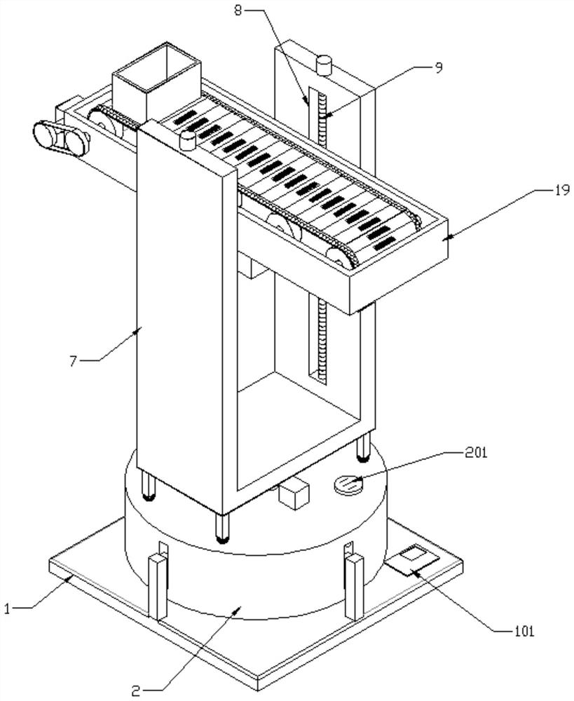
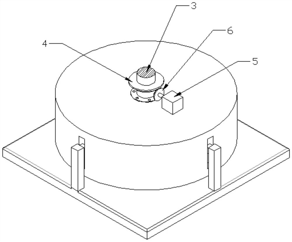
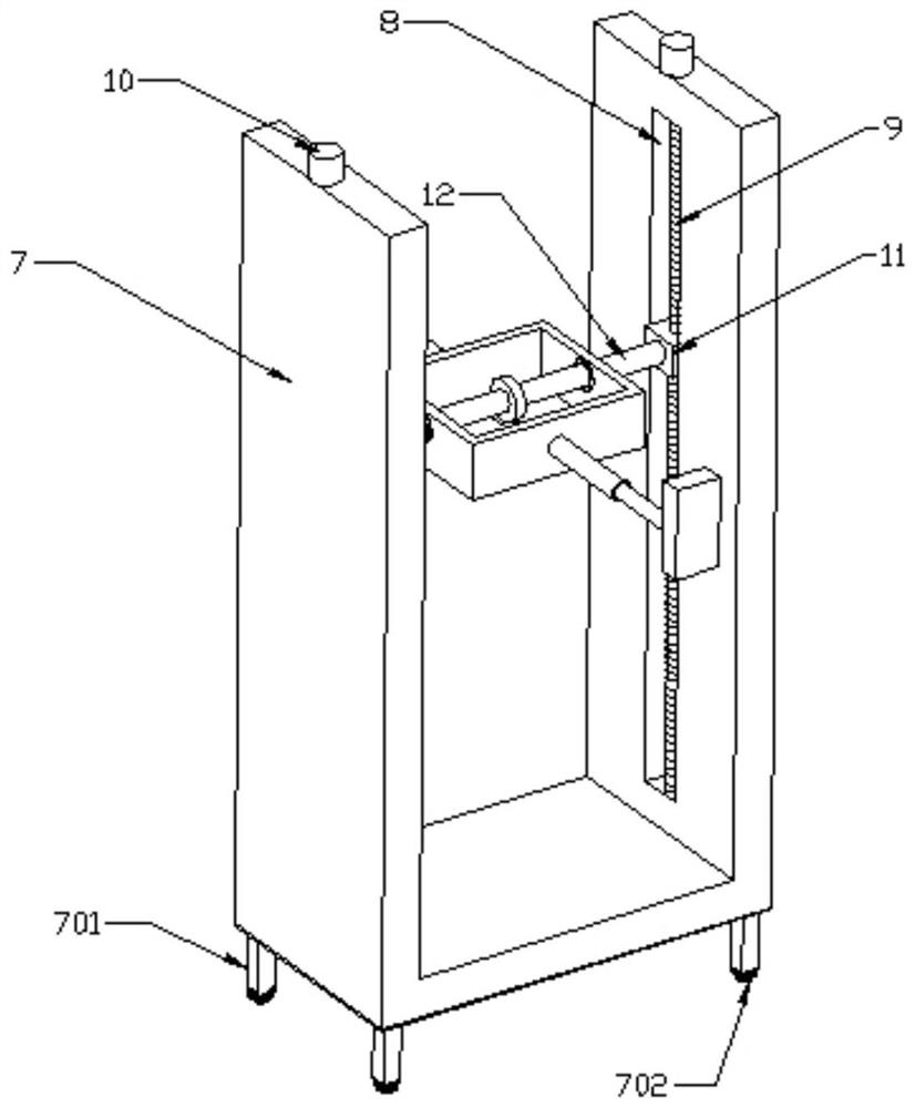
[0029] see Figure 1-6 As shown, this embodiment is a construction unloading platform with an IC, including a base 1, a shock-absorbing seat 2 is arranged above the base 1, and a support column 3 is connected to the center of the top of the shock-absorbing seat 2 in rotation. , the outer wall of the support column 3 is connected with a bevel gear 4, the top of the shock absorber 2 is connected with a first motor 5, the power output end of the first motor 5 is connected with a bevel gear 6, and the bevel gear 6 meshes with the bevel gear 4 , the top of the support column 3 is connected with a U-shaped seat 7, and the inner side wall of the U-shaped seat 7 is symmetrically opened with a limit groove 8, and the limit groove 8 is connected with a screw rod 9 for rotation, and the upper end of the screw rod 9 is connected with a second motor. 10. The outer wall of the screw rod 9 is screwed with a nut seat 11, and a steering shaft 12 is connected between the two sets of nut seats 1...
Embodiment 2
[0033]On the basis of Embodiment 1, a buzzer 201 is connected to the upper part of the outer wall of the shock-absorbing seat 2, four groups of chute 202 are opened in the lower part of the outer wall of the shock-absorbing seat 2 in the circumferential direction, and the top of the inner cavity of the left chute 202 A push switch 203 is connected, the press switch 203 is connected in series with the buzzer 201 circuit, a slider 204 is slidably connected in the chute 202, and one end of the slider 204 protruding from the chute 202 is connected with a vertical rod 205, and the lower end of the vertical rod 205 is fixedly connected to the Several groups of shock-absorbing springs 206 are evenly distributed between the upper surface of the base 1 and the top of the inner chamber of the shock-absorbing seat 2 and the upper surface of the base 1 .
[0034] The left side wall of unloading frame 19 is connected with the 4th motor 191, and the inner chamber of unloading frame 19 is con...
Embodiment 3
[0040] On the basis of Embodiment 2, the four corners of the bottom of the U-shaped seat 7 are connected with support columns 701, and the bottom of the support column 701 is equipped with a universal ball head 702, and the lower end of the universal ball head 702 abuts against the upper surface of the shock absorber 2, Able to provide auxiliary support.
[0041] The unfolding helix angle of the worm 16 is smaller than the contact friction angle of the worm wheel 13 and the worm 16 , which can realize the self-locking effect and prevent the bearing frame 14 from shaking.
[0042] The driving shaft 192 and several groups of driven shafts 196 are arranged in parallel along the length direction of the unloading frame 19 to facilitate the operation of the transmission chain 198 .
[0043] The outer wall of the base 1 is connected with an IC controller 101, and the IC controller 101 is electrically connected to the first motor 5, the second motor 10, the third motor 15, the hydraul...
PUM
 Abstract
Description
Claims
Application Information
 - Generate Ideas
- Intellectual Property
- Life Sciences
- Materials
- Tech Scout
- Unparalleled Data Quality
- Higher Quality Content
- 60% Fewer Hallucinations
Browse by: Latest US Patents, China's latest patents, Technical Efficacy Thesaurus, Application Domain, Technology Topic, Popular Technical Reports.
© 2025 PatSnap. All rights reserved.Legal|Privacy policy|Modern Slavery Act Transparency Statement|Sitemap|About US| Contact US: help@patsnap.com