
Decoupling type electric brake booster

A technology of electric braking and brake boosting, which is applied in the direction of brakes, brake transmissions, transportation and packaging, etc., can solve the problems of driver's bad feeling and affect the transmission efficiency of brake boosting, and achieve the goal of avoiding bad feeling Effect

Pending Publication Date: 2021-07-16
ROBERT BOSCH GMBH
View PDF0 Cites 2 Cited by
  • Summary
  • Abstract
  • Description
  • Claims
  • Application Information

AI Technical Summary

Problems solved by technology

This affects the efficiency with which the brake boost is delivered and may also give the driver a bad feeling with their foot on the brake pedal

Method used


Image

  • Decoupling type electric brake booster
  • Decoupling type electric brake booster
  • Decoupling type electric brake booster

Examples


Embodiment Construction

[0017] Some possible implementations of the present application are described below with reference to the accompanying drawings. It should be pointed out that the accompanying drawings are only for reflecting the principle of the application, rather than showing the actual structure of the application. Accordingly, the drawings are not to scale; and, for clarity, some details are exaggerated and others omitted.

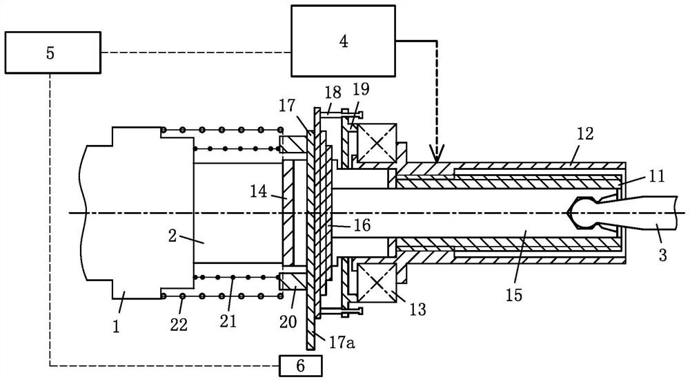
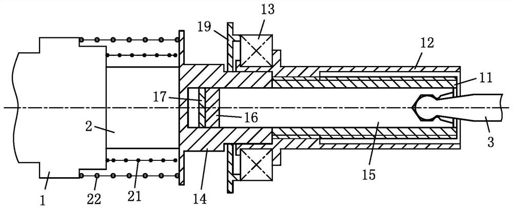
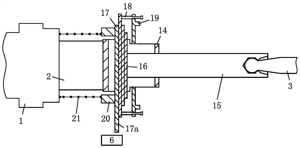
[0018] First of all, it needs to be pointed out that in this application, "rear side" refers to the side kinematically close to the brake pedal of the vehicle, and "front side" refers to a side kinematically away from the brake pedal, that is, close to the brake master cylinder. side.

[0019] Such as figure 1 , 2 As shown, a decoupled electric brake booster used in a vehicle braking system according to a possible implementation of the present application is used to transmit output force to the piston 2 of the brake master cylinder 1 of the vehicle hydraulic brakin...


PUM


Abstract

An electric brake booster for use in a vehicle includes: a pedal force transmission mechanism configured to be driven to move in an axial direction by a brake pedal; a detection device configured to detect an action of the pedal force transmission mechanism; a braking motor which is configured to be suitable for executing motor braking operation so as to generate braking assistance; an assisting power transmission mechanism which is configured to be suitable for being driven by a brake motor (4) to move in the axial direction so as to transmit brake assisting power generated by the brake motor to a piston of the brake master cylinder, wherein, in the motor braking operating mode, the assist force transmission mechanism is kinematically decoupled relative to the pedal force transmission mechanism, and only the brake assist force generated by the brake motor forms the input force of the electric brake booster.

Description

technical field [0001] The present application relates to an electric brake booster for use in a vehicle braking system, wherein the brake motor has a separate brake boosting transmission line decoupled from the pedal force transmission line. Background technique [0002] Many vehicles add a brake booster to their hydraulic braking system. Brake boosters generally include vacuum boosters and electric boosters. The vacuum booster uses the vacuum of the engine intake pipe as the source of brake booster, and the electric booster uses the motor as the source of brake booster. [0003] In the existing electric booster, the brake booster and the pedal force usually have a coupled transmission line, that is, they are transmitted to the brake master cylinder piston through a common force transmission element. For such an electric booster, when the driver performs a braking operation, the driver depresses the brake pedal to apply pedal force, the motor of the electric booster gener...

Claims


Application Information

Patent Timeline
IPC IPC(8): B60T13/74
CPCB60T13/745
Inventor 章秋生
Owner ROBERT BOSCH GMBH
Learn More