
Lighting equipment for ophthalmic examination

A lighting equipment, ophthalmic examination technology, applied in surgical equipment, eye testing equipment, surgical lighting, etc., can solve the problems of single examination results, delayed examination time, slow speed, etc., to improve work efficiency, lighting stability, operation handy effect

Active Publication Date: 2021-07-16
THE AFFILIATED HOSPITAL OF QINGDAO UNIV
View PDF4 Cites 0 Cited by
  • Summary
  • Abstract
  • Description
  • Claims
  • Application Information

AI Technical Summary

Problems solved by technology

[0003] Eye examinations are usually divided into ophthalmic examinations and optometry examinations. However, the two examinations have independent intervals and equipment. The examination results are single, the process is cumbersome and repetitive, the efficiency is low, and the speed is slow. It does not meet the fast-paced work and life of modern society. Require
At present, when doctors conduct ophthalmological examinations, they usually carry out inspections with hand-held lights, which invisibly delays the examination time and reduces the work efficiency of the examiners.

Method used


Image

  • Lighting equipment for ophthalmic examination
  • Lighting equipment for ophthalmic examination
  • Lighting equipment for ophthalmic examination

Examples


Embodiment 1

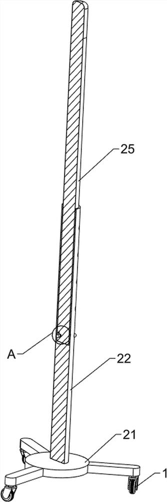
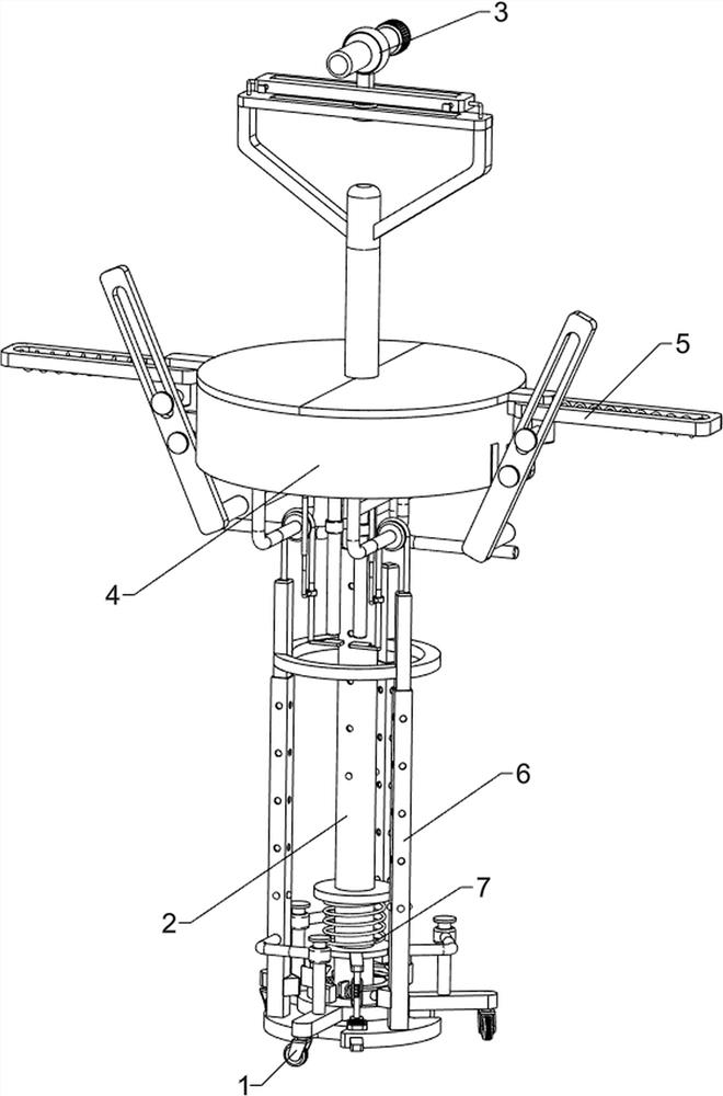
[0030] A lighting device for ophthalmic examination, such as figure 1 , figure 2 , image 3 with Figure 4 Shown, comprise moving wheel 1, regulating mechanism 2 and lighting mechanism 3, moving wheel 1 has three, and the rotating type between moving wheel 1 top is provided with regulating mechanism 2, and regulating mechanism 2 upper side is provided with lighting mechanism 3.

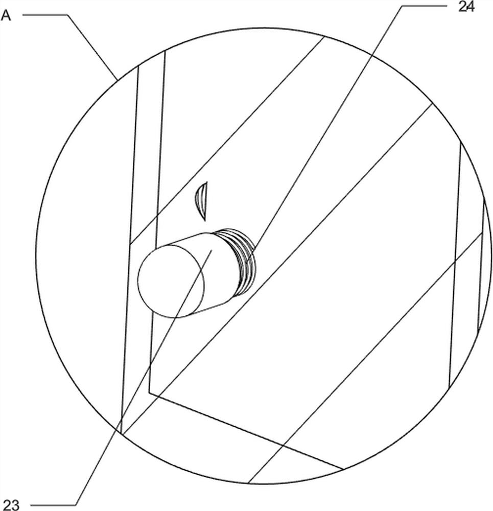
[0031] The adjustment mechanism 2 includes a first connecting plate 21, a first telescoping rod 22, a first block 23, a first spring 24 and a first connecting rod 25, and the first connecting plate 21 is rotatably arranged between the top of the moving wheel 1, The top of the first connecting plate 21 is provided with a first telescopic rod 22, the upper side of the first telescopic rod 22 is slidingly provided with a first connecting rod 25, and the lower side of the first connecting rod 25 is slidingly provided with three first blocks 23 at even intervals A plurality of circular holes are evenly...

Embodiment 2

[0035] On the basis of Example 1, such as Figure 5 , Image 6 , Figure 7 , Figure 8 with Figure 9 As shown, it also includes a placement assembly 4, the placement assembly 4 includes a second connecting rod 41, a first baffle plate 42, a placement plate 43, a first fixing rod 44, a first push rod 45 and a second push rod 46, the first push rod 45 and the second push rod 46. The rear side of a connecting rod 25 middle part is provided with a second connecting rod 41, and the front side of the second connecting rod 41 top is provided with a first baffle plate 42, and the first baffle plate 42 is slidably provided with a placement plate 43, and the placement plate 43 is connected to the first baffle plate 42. A connecting rod 25 is slidably matched, and the front side of the first connecting rod 25 is symmetrically provided with a first fixed rod 44, and the front side of the bottom of the placement plate 43 is symmetrically provided with a first push rod 45, and the first...


PUM


Abstract

The invention relates to lighting equipment, in particular to lighting equipment for ophthalmic examination. The technical problem to be solved by the invention is to provide the lighting equipment for ophthalmologic examination, which is convenient to move and operate. According to the technical scheme, the lighting equipment for ophthalmologic examination comprises three moving wheels, an adjusting mechanism and a lighting mechanism, wherein the adjusting mechanism is rotationally arranged between the tops of the moving wheels; and the lighting mechanism is arranged on the upper side of the adjusting mechanism. The lighting equipment has the beneficial effects that under the action of the lighting mechanism, people can move a first sliding rod left and right, the first sliding rod can drive a second clamping block and a lighting lamp to move left and right, when people adjust the device to a proper position, a pull rod is moved backwards, the pull rod can drive a clamping groove to move backwards, and when the clamping groove is in contact fit with the second clamping block, the first sliding rod and the lighting lamp are fixed, so that the lighting lamp is more stable when people carry out ophthalmic examination.

Description

technical field [0001] The invention relates to a lighting device, in particular to a lighting device for ophthalmic examination. Background technique [0002] With economic development and social progress, people pay more and more attention to their health, especially eye diseases, so people will check their eyes regularly. [0003] Eye examinations are usually divided into ophthalmological examinations and optometry examinations. However, the two examinations have independent intervals and equipment. The examination results are single, the process is cumbersome and repetitive, the efficiency is low, and the speed is slow. It does not meet the fast-paced work and life of modern society. Require. At present, when doctors conduct eye examinations, they generally carry out inspections with hand-held lights, which invisibly delays the examination time and reduces the work efficiency of the examiners. [0004] Therefore, it is urgent to propose a convenient and easy-to-operate...

Claims


Application Information

Patent Timeline
IPC IPC(8): A61B50/22A61B90/35A61B3/00
CPCA61B50/22A61B90/35A61B3/0008Y02B20/40
Inventor 徐剑亮
Owner THE AFFILIATED HOSPITAL OF QINGDAO UNIV
Learn More